
Three-Phase Motor Intelligent Monitoring and Control Solution
1. Background
In industrial production, three-phase motors are the core power source that drives mechanical equipment, and whether they run stably directly affects whether production runs smoothly and determines product quality and production efficiency. Traditional motor management relies on manual inspection and on-site operation. It is time-consuming, leaves blind spots, and cannot detect subtle anomalies in real time, so equipment faults easily interrupt production. Shanghai Daq IoT Technology Co., Ltd. has therefore drawn on advanced IoT, sensor and data analytics technology to build a complete intelligent monitoring and precise control solution for three-phase motors. It combines operating current and energy monitoring, vibration and temperature monitoring, rotational speed monitoring, and remote start/stop control, enabling the intelligent transformation of motor management in industrial enterprises.
2. Solution Architecture
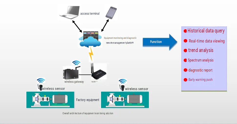
The solution is built on four cooperating layers: perception, transmission, data processing and application. The perception layer places high-precision sensors against key points on the motor to capture operating data accurately. The transmission layer uses 4G, WiFi, LoRa and other networks to upload the data securely and quickly to the cloud. The data processing layer applies cloud computing and big data analytics to mine and interpret the data at scale. The application layer gives users purpose-built web and mobile interfaces that show motor status clearly and enable remote control and intelligent management.
3. Functions
(1) Operating Current and Energy Consumption Monitoring
Device selection: the DAQ-GP-EM4G wireless power monitor is the core device for current and energy monitoring. It integrates a precision current transformer and signal conditioning circuitry, clamps onto the power cable of the three-phase motor and acquires line current accurately.
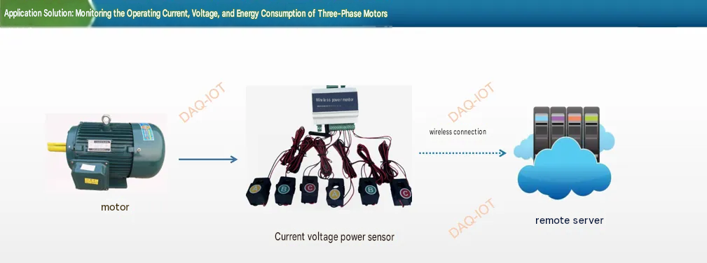
Parameter calculation: a high-performance microprocessor inside the monitor uses dedicated algorithms to calculate active power, apparent power, power factor and operating frequency in real time from the current data. Active power, for example, is derived from the phase difference between current and voltage and the RMS current, and power factor from the ratio of active to apparent power.
Anomaly warning: a normal current band is configured in the software. When the measured current leaves the preset range, whether overcurrent (a sharp rise when the motor stalls, for example) or undercurrent (which a missing phase can cause), the alarm routine triggers immediately and the data processing layer pushes the alarm to the application layer, notifying O&M staff by pop-up, SMS or email.
(2) Vibration and Temperature Monitoring
Vibration and Temperature Monitoring
Sensor installation: the SC-LP-VIB low-power wireless vibration sensor mounts magnetically or with a clip and attaches easily to the motor housing near bearings, the base and other points prone to vibration. It does not alter the motor structure, so data acquisition is non-intrusive.
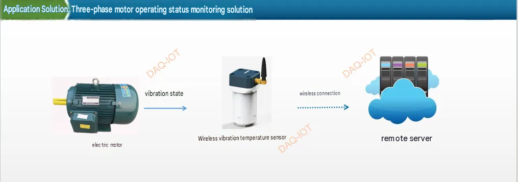
Data acquisition: the sensor contains a high-performance MEMS vibration element that picks up the vibration the motor produces. The acquisition interval can be set to suit motor behavior. Shortly after start-up, for example, shorten it to once per second to capture the vibration at the moment of starting precisely; in normal operation, set it to once every 10 seconds to balance data volume against monitoring quality.
Data transmission: the sensor carries a 4G/NB-IOT/LoRa communication module. It packages the vibration data in the agreed protocol and sends it over the wireless network to a nearby base station or gateway, which relays it to the server. Encryption protects the data in transit against leakage or tampering.
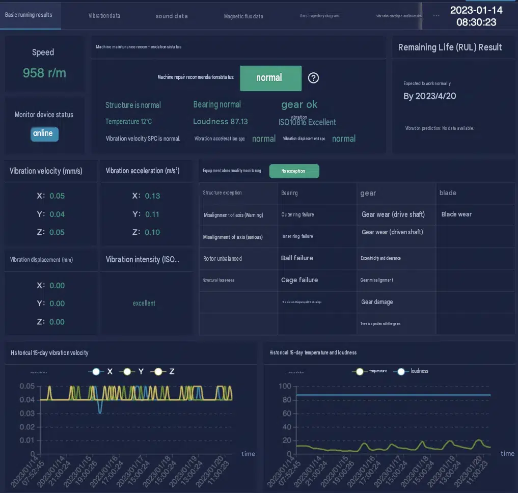
Fault diagnosis: on the server, vibration spectrum analysis, time-domain analysis and similar algorithms interpret the data. When characteristic parameters such as amplitude or frequency leave the normal range, the system identifies likely mechanical faults such as bearing wear, rotor imbalance or a loose foundation, and generates a detailed fault report for the application layer, giving maintenance staff a sound basis for repair planning.
Standalone Temperature Monitoring
Measurement principle: the SC-GP-PT100 wireless industrial temperature transmitter converts thermocouple or RTD signals into an input signal or a measured temperature and reports the motor surface temperature at set intervals over GPRS or 4G.
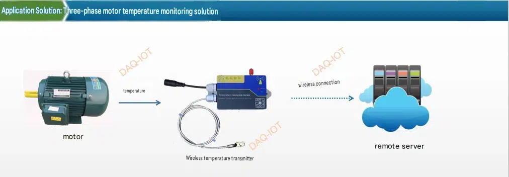
Multi-point acquisition: the sensor supports multiple independent temperature channels, which can be distributed evenly around the motor housing and other heat-prone areas for all-round temperature monitoring. Measurement accuracy is within ±0.5 °C, meeting strict accuracy requirements under different operating conditions.
Threshold alarms: in the application layer, users set temperature alarm thresholds according to motor type, operating environment and other factors. When a channel approaches or exceeds its threshold, the data processing layer responds quickly and pushes a high-temperature warning, prompting staff to check causes such as a failed cooling fan or excessive load.
(3) Rotational Speed Monitoring
Measurement principle: the SC-GP-RPM4G wireless speed detector uses the Hall effect. A magnetic body (a magnetic patch, for example) is fitted near the rotating shaft, and as the motor turns it passes the detector’s Hall element periodically. The Hall element responds to the changing field and outputs a pulse signal related to rotational speed.
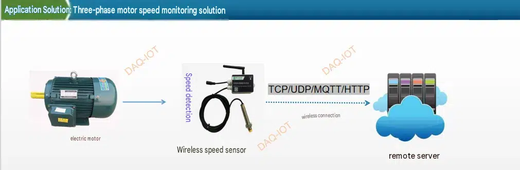
Signal processing: a high-precision counter and signal conditioning circuit inside the detector amplify and shape the pulses from the Hall element and count pulses per unit time precisely. Given the pulses produced per revolution (60 measurement points per revolution, for example, giving 60 pulses per turn) and the counting period, the speed formula (rotational speed = pulse count ÷ time × 60) yields the motor speed in real time.
Applications: on a production line, abnormal motor speed reduces machining accuracy and disrupts takt time. In textiles, unstable speed makes yarn thickness uneven; in food packaging, it causes packaging dimension errors. By monitoring speed in real time, the system raises an alarm as soon as speed fluctuation exceeds the preset range (for example beyond ±5%), so operators can adjust motor parameters or check factors that affect speed, such as a slack drive belt or a faulty gearbox.
(4) Remote Start/Stop Control
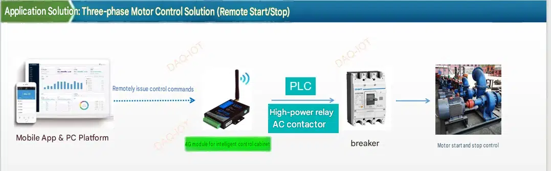
Hardware: the intelligent control cabinet is the hardware core of remote start/stop control. It contains a programmable logic controller (PLC) and high-power relays or AC contactors. The PLC receives and interprets control commands, while the relays or contactors switch the motor power circuit. They are highly reliable and carry high currents, and suit three-phase motors of different power ratings.
Communication: the control cabinet connects to the internet through a 4G IoT module and maintains a stable link to the cloud server. WiFi, Ethernet and other wired options serve as backups to keep communication continuous. MQTT and other lightweight, efficient IoT protocols carry the commands promptly and reliably.
Access control: a dedicated user management system in the application layer assigns different permissions by role. Administrators, for example, hold full rights for remote start/stop, parameter settings and user management, while general operators can only start and stop motors. At login, the system applies multi-factor authentication such as account password plus SMS code, so operations are safe and illegal actions cannot cause production incidents.
Control flow: the user taps start or stop in the mobile app or web interface. The command travels over the internet to the cloud server, which forwards it to the control cabinet of the relevant motor. The PLC receives it and operates the relay according to preset logic, closing or opening the motor power circuit to start or stop the motor remotely. The cabinet reports the motor status back to the cloud server in real time, and the server syncs it to the user interface so the user can confirm the result.
4. Advantages
Real-time performance: the high-speed 4G network and optimized data protocols hold latency from sensor acquisition to the user interface to under 1 second, so users always see the latest motor status and can react to incidents quickly.
Easy installation: the wireless sensors and control cabinet are designed for convenient installation. The sensors are plug-and-play with magnetic or clip mounting and need no complex cabling. The cabinet has standardized interfaces and connects quickly to existing electrical systems, which shortens installation and commissioning and lowers project cost.
Intelligent warning: big data analytics and machine learning mine multi-source motor data to build fault prediction models. The system detects current faults and can also predict potential failures 7-15 days ahead, giving the enterprise time to schedule preventive maintenance and reducing production losses and repair costs from sudden failure.
Remote operation: location no longer matters. Wherever the user’s device has internet access, in the office, on a business trip or at a plant in another city, motors can be started, stopped and adjusted from a phone or PC, making motor management intelligent and efficient.
5. Application Scenarios
The solution suits the power, metallurgy, petrochemical and paper industries and any industrial enterprise that runs three-phase motors. In power, it provides centralized monitoring and remote control of generation equipment and transmission and distribution motors, supporting stable supply. In metallurgy, real-time visibility of blast furnace fans and rolling mill motors improves efficiency and product quality. In petrochemical plants, precise control of reactor agitator motors and pump motors keeps chemical production safe and efficient. In paper mills, monitoring and control of paper machine motor speed, temperature and other parameters keeps production continuous and quality stable. On construction sites, it simplifies management of tower crane, hoist and other construction equipment motors, supporting schedule and safety.
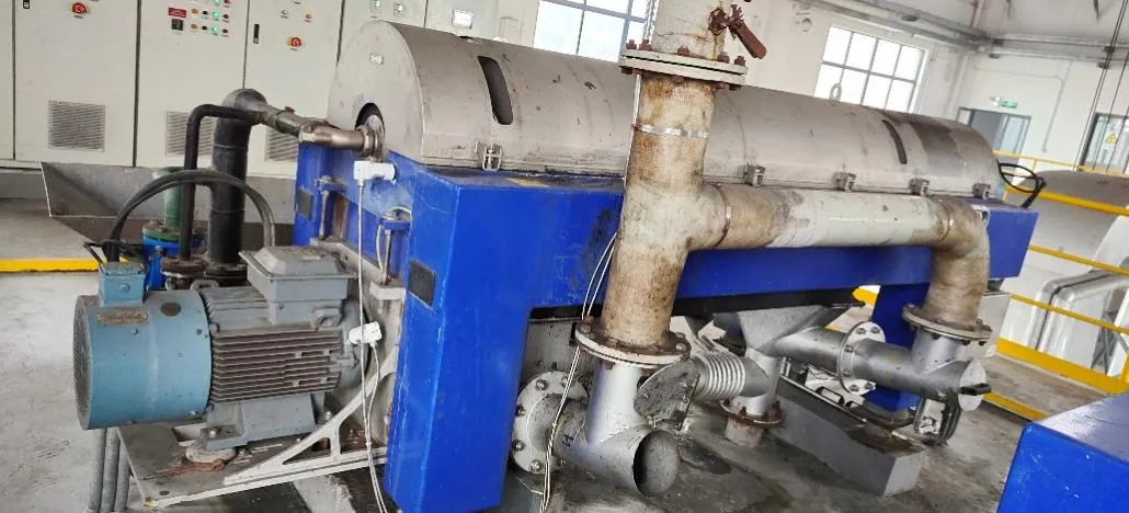
Water treatment case: sewage treatment equipment and the rotating equipment in a wastewater treatment plant, including water pumps, dewatering machines, sewage pumps and blowers.
Metallurgy case: apron feeders, trough conveyors, bucket elevators, high-temperature fans, roller presses, rotary kilns, vertical mills, ball mills, belt conveyors, crushers, separators, grate coolers, double-roll crushers and more.
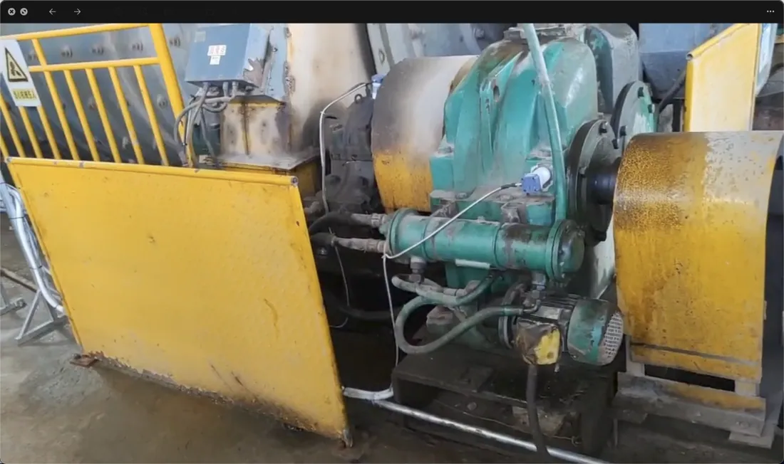
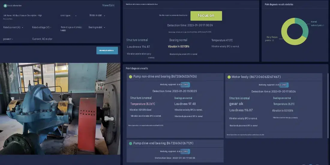
The three-phase motor monitoring and control solution from Shanghai Daq IoT Technology Co., Ltd. gives users a complete, efficient and reliable way to manage motors, helping enterprises raise production efficiency, cut O&M costs and complete their intelligent transformation.