
| Project | Wireless monitoring system for predictive maintenance of the pump fleet |
|---|---|
| Document type | Construction and design plan |
| Version | V1.0 |
| Prepared by | Shanghai Daq IoT Technology Co., Ltd. |
| Date | 2026 |
1. Project Overview
1.1 Background
This project builds a wireless monitoring system for predictive maintenance of the motor and pump fleet at a chemical plant. In a chemical production unit, motor-driven pumps of every kind — centrifugal, canned-motor, transfer pumps and others — are core drive equipment. An unexpected stop interrupts production and can cause a safety incident, with very large losses.
Wireless vibration and temperature sensors are installed at key points on the motors and pump bodies. They collect vibration acceleration and temperature data and feed an industrial equipment predictive maintenance platform, which gives real-time visibility of equipment condition and early fault warnings. Maintenance moves from scheduled repair to predictive repair.
1.2 Site Equipment
The on-site equipment survey list defines the following equipment types for this monitoring scope:
| Tag No. | Description | Pump model | Motor power | Speed | Control |
|---|---|---|---|---|---|
| P-301B | Butyl acrylate transfer pump | XQ-8/25-200*2 | 11 kW | 2940 rpm | VFD |
| P-301C | Butyl acrylate unloading/transfer pump | IMZ80-50-160 | 11 kW | 2940 rpm | VFD |
| P-303B | Styrene transfer pump | IMZ65-40-315L | 37 kW | 2950 rpm | VFD |
| P-303C | Styrene transfer pump | IMZ65-40-315L | 37 kW | 2950 rpm | VFD |
| P-2104A | Butadiene canned-motor pump | PN50-300/A33B | 18.5 kW | 2900 rpm | VFD |
| P-2104B | Butadiene canned-motor pump | PN50-300/A33B | 18.5 kW | 2900 rpm | VFD |
| P-201A | Butadiene unloading pump | R0508V-516 | 18.5 kW | Fixed speed | |
| P-201B | Butadiene unloading pump | N72-412JBM | 18.5 kW | Fixed speed | |
| C-202 | Butadiene compressor | ZW-1.5/10-16 | 22 kW | 730 rpm | Fixed speed |
| P-108B | Circulating water pump | 12SH-9 | 110 kW | 1490 rpm | VFD |
| C-206 | Incinerator combustion air fan | YB3-132S2-2 | 7.5 kW | 2910 rpm | Fixed speed |
| P-304 | Acrylic acid transfer pump | YBX3-132S2-2W | 7.5 kW | 2900 rpm | Fixed speed |
(The table is longer; only the first 12 rows are shown here.)
Note: these units are spread across the latex pump shelter area, the latex unit area, the butadiene pump shelter area, the circulating water pump house and the incinerator area. All are in explosion-hazardous areas (Zone 1/Zone 2), so sensors and gateways must hold the corresponding explosion-proof certification.
1.3 Design Objectives
● Real-time acquisition of vibration (three-axis acceleration) and temperature on every monitored pump and motor, with an acquisition interval of ≤5 minutes
● Wireless coverage of all pump areas, stable gateway-to-platform transfer, packet loss <1%
● Sensors installed to specification and compliant with explosion-proof requirements, without affecting normal equipment operation
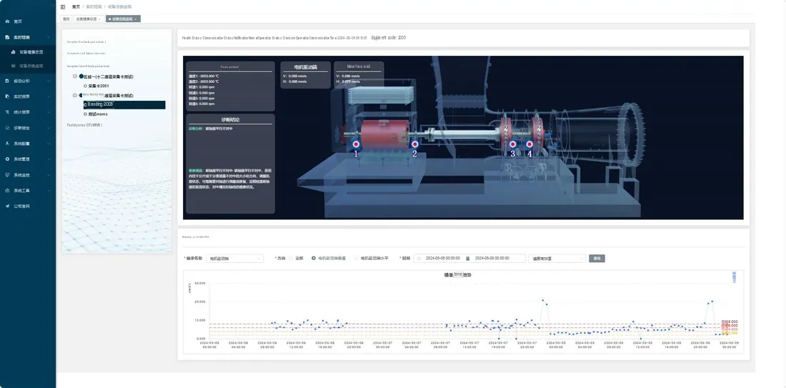
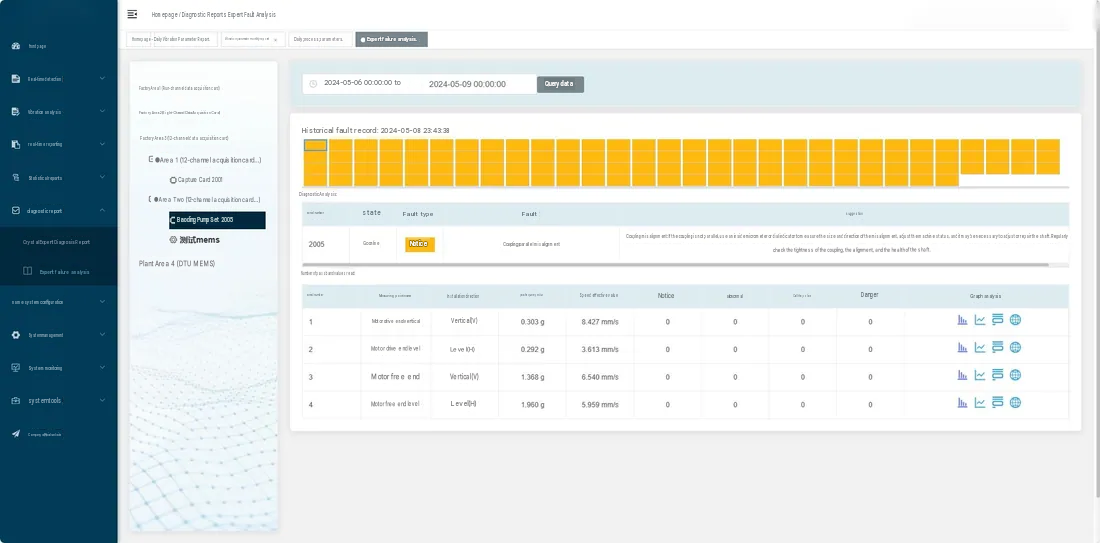
● After go-live, connection to the predictive maintenance platform for fault alerts and historical trend analysis
● Construction executed under the plant’s work permit system, with zero safety incidents
2.1 Overall Architecture
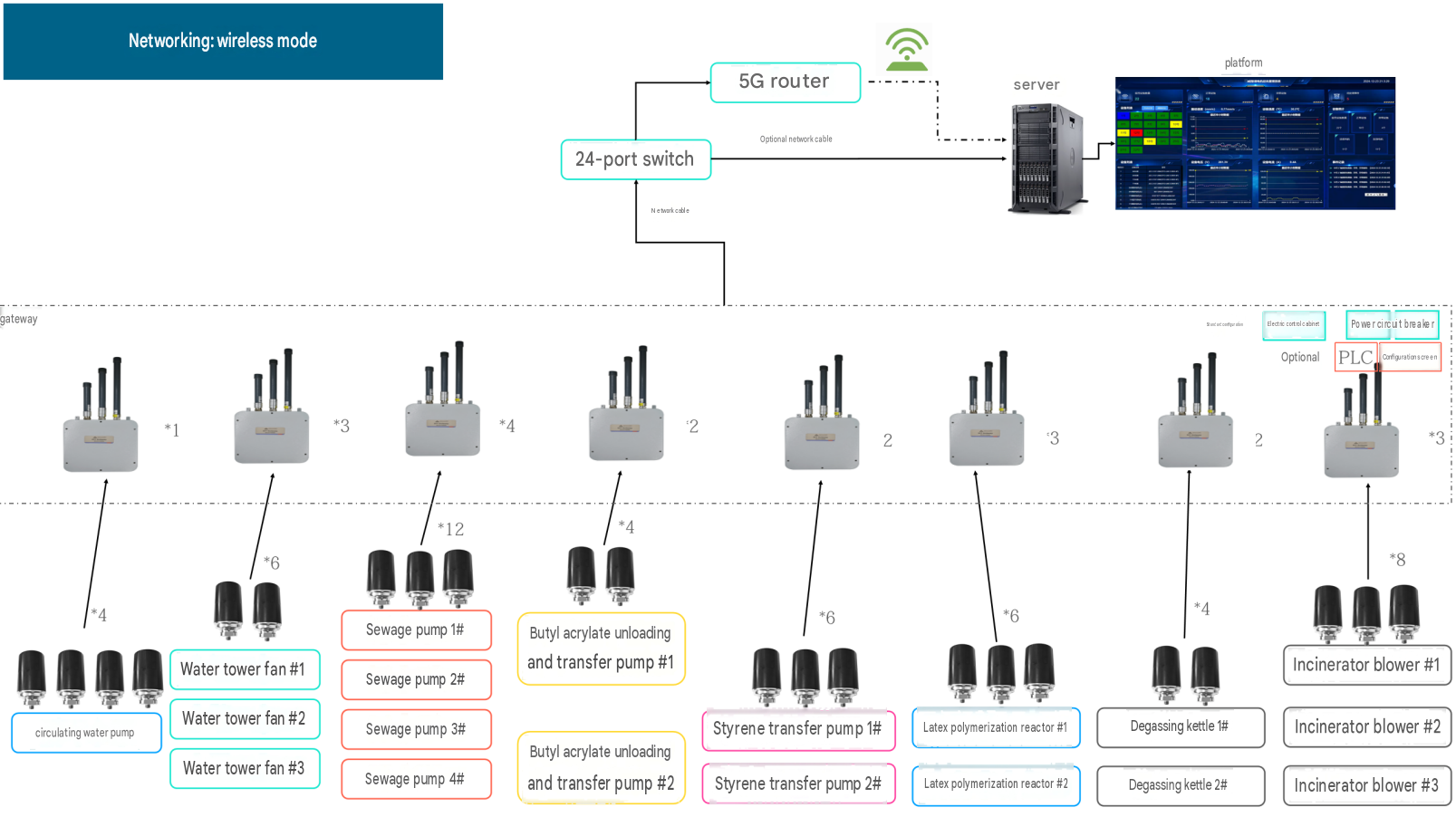
The system uses a four-layer wireless architecture: sensor → explosion-proof wireless gateway → 5G router → platform server. No signal cabling is needed at any layer, which keeps installation simple and minimizes disruption to production.
| Layer | Core equipment | Location | Main function |
|---|---|---|---|
| Perception | Intrinsically safe wireless vibration and temperature sensor | Motor bearing housing / pump body | Vibration and temperature acquisition |
| Aggregation | Explosion-proof wireless gateway (Exd IIC T4 Gb) | Wall-mounted near each pump area | Wireless data aggregation and forwarding |
| Transport | 5G/LTE industrial router (wired Ethernet optional) | Near the electrical room or control room | Remote data transmission |
| Platform | Predictive maintenance industrial equipment health management platform | Enterprise intranet or cloud | Data analysis and early warning display |
2.2 Wireless Communication
Sensors and the explosion-proof gateway communicate over a Sub-1GHz industrial wireless protocol in the 470–510 MHz band. Strong penetration and good immunity to interference suit the dense metal piping of a chemical plant building.
One gateway accepts up to 37 sensor nodes (this project plans 8–16 sensors per gateway), with a coverage radius of about 100–300 m depending on obstructions. Gateway count and position are adjusted to the actual site survey.
2.3 Explosion-Proof Zoning and Equipment Selection
The plant unit is an explosive gas atmosphere, hazardous area Zone 1/Zone 2, with gas group IIC predominant (butadiene, styrene, acrylic acid and similar).
| Equipment | Model | Ex marking | Certificate No. | Protection type |
|---|---|---|---|---|
| Vibration and temperature sensor | Ex ia IIC Ga / Ex ia IIC T₄ₘ₁ Db | / | Intrinsic safety ib/ia | |
| Explosion-proof gateway enclosure | Ex junction box BJX | Ex db IIB T6 Gb / Ex db IIC T6 Gb | SYEx24.0303 | Flameproof d |
3. Equipment and Material List
3.1 Main Equipment
| No. | Equipment / material | Brand / spec | Unit | Qty | Remarks |
|---|---|---|---|---|---|
| 1 | Wireless vibration and temperature sensor | Daq IoT | unit | 13+16+8=37 | Includes mounting magnet / stud base |
| 2 | Explosion-proof wireless gateway (with enclosure) | Matching product | unit | 3 | Includes BJX Ex junction box, Exd IIC |
| 3 | 5G industrial router | Matching product | unit | 1 | Includes antenna and SIM card |
| 4 | Power cable (shielded) | m | As measured | ZR-KVVP 2×1.5 mm², flame-retardant, shielded | |
| 5 | Expansion bolt M10 | set | As required | For wall-mounting the gateway enclosure | |
| 6 | Stainless steel pipe clamp / cable tie | set | As required | Cable fixing | |
| 7 | Grounding copper conductor | m | As required | 4 mm² green/yellow insulated wire | |
| 8 | Cable conduit (KBG / galvanized) | m | As measured | DN20, for power cable protection | |
| 9 | Stainless steel tag plate | plate | 37 | Sensor tag identification |
3.2 Sensor Specifications
| Parameter | Value |
|---|---|
| Ex marking | Ex ia IIC Ga / Ex ia IIC T₄ₘ₁ Db |
| Certificate | / |
| Vibration range | 0–200 m/s² (acceleration), 0–10 mm/s (RMS velocity) |
| Frequency response | 10–5000 Hz (−3 dB) |
| Temperature range | 40 °C to +125 °C |
| Temperature accuracy | ±1 °C |
| Wireless | Sub-1GHz, 470–510 MHz |
| Power supply | Built-in lithium thionyl chloride battery (>3-year life; 3.6 V external supply supported) |
| Protection rating | IP68 |
| Mounting | Magnetic base / M8 stud |
| Dimensions | φ36 × 78 mm (approx.) |
| Operating temperature | 40 °C to +85 °C (ambient) |
3.3 Gateway Enclosure Specifications
| Parameter | Value |
|---|---|
| Protection type | Exd flameproof (BJX) |
| Ex marking | Ex db IIB T6 Gb / Ex db IIC T6 Gb / Ex tb IIIC T80 °C Db |
| Rated voltage / current | AC 380 V / 220 V, 200 A |
| Dimensions | 200 × 318.95 × 57.2 mm (W × H × D) |
| Mounting hole spacing (width) | 155.6 mm, hole diameter φ4 mm |
| Protection rating | IP66 |
| Antenna ports | 3 × external SMA antennas (LoRa / Wi-Fi / 5G optional) |
| Power supply | AC 220 V, tapped from the nearest existing supply point |
| Certification standards | GB/T 3836.1-2021 / GB/T 3836.2-2021 / GB/T 3836.31-2021 |
4. Sensor Installation Plan
4.1 Point Selection Principles
Monitoring points are chosen close to the bearing, on a short force-transmission path and where the vibration signal is strong, so the measured signal truly reflects bearing and rotor condition.
● Horizontal/radial (H): on the side of the drive-end or non-drive-end bearing housing, horizontal, at either the 90° clockwise or counterclockwise position
● Vertical/axial (V/A): add an axial point where conditions allow, to detect axial float and misalignment
● Pump-side point: on the pump body close to the bearing, or on the pump-end bearing housing opposite the coupling
● Canned-motor pumps: on the outer casing wall near the bearing end cover (where the bearing housing cannot be reached), held firmly by a magnetic base
● Avoid hot areas (>85 °C), greased surfaces and thick paint (>3 mm); grind to bare metal before mounting
4.2 Mounting Methods
▶ 4.2.1 Magnetic base mounting (preferred)
For ferromagnetic housings (cast iron, carbon steel), the sensor’s strong magnet attaches directly. The operation is simple, needs no drilling and does no damage to the equipment.
Mounting requirements:
○ 1. Clean the mounting area and grind with an angle grinder or abrasive paper to bright metal (Ra ≤ 3.2 μm)
○ 2. Fit the magnet to the sensor and press it squarely onto the point; confirm it holds firm and does not shift when gently pushed
○ 3. Tie the sensor lead with cable ties or wire so that vibration cannot fatigue the cable
○ 4. Fit the tag plate, photograph the installation and file the record
▶ 4.2.2 Stud mounting (higher stability)
For stainless steel equipment (canned-motor pump casings) or where magnetic holding force is insufficient, use a welded or tapped M8 stud.
○ 1. Confirm the position, mark the M8 center hole and clean the surface
○ 2. If welding is permitted: pre-weld the M8 stud (welding requires a plant hot-work permit)
○ 3. If welding is not permitted: tap an M8 threaded hole in the bearing housing or an auxiliary bracket, depth ≥ 12 mm
○ 4. Fit the sensor base and tighten with a torque wrench to 8–12 N·m
○ 5. Apply a little threadlocker (Loctite 243) to prevent loosening under vibration
4.3 Installation Points by Equipment Type
| Equipment type | Installation points |
|---|---|
| Centrifugal pumps (P-301/303/108/304/303A) | Single-side mounting on the drive-end bearing housing of the motor, horizontal; add a non-drive-end point where possible. Pump end mounted on the pump body near the bearing. |
| Canned-motor pumps (P-2104A/B) | The closed construction leaves only the outer wall of the front and rear bearing end covers; use a magnetic base or an M8 stud. Vibration is relatively low, so raise the sensor sensitivity. |
| Unloading pumps (P-201A/B) | Per the site photos, mount on the side of the pump body near the outlet, magnet-mounted. If the body is stainless steel, switch to stud mounting. |
| Compressor (C-202) | Mount on the bearing housings at both ends of the crankcase. At 730 rpm, prioritize low-frequency vibration (10–1000 Hz). |
| Fan (C-206) | Mount on the bearing housings at both ends of the motor and record the operating state (start/stop times). |
4.4 Number of Installation Points
Based on the site equipment list (13 units in total) and the actual monitoring needs, the recommended points are:
| Equipment type | Point description | Points | Area |
|---|---|---|---|
| Centrifugal pumps (5) | 2 per unit (motor drive end + pump end) | 10 | Latex pump shelter area / circulating water pump house |
| Canned-motor pumps (4) | 2 per unit (front/rear bearing end covers) | 8 | Latex unit area / butadiene pump shelter area |
| Unloading pumps (2) | 2 per unit (motor + pump body) | 4 | Butadiene pump shelter area |
| Compressor (1) | 2 per unit (both ends of the crankcase) | 2 | Butadiene area |
| Fan (1) | 2 per unit (both ends of the motor) | 2 | Incinerator area |
| Total | 26 | Compared with the 37-point scheme; more can be added as needed |
5. Explosion-Proof Gateway Installation Plan
5.1 Siting Principles
● Mount on an unobstructed wall near the pump area, with a wireless distance to the sensor group of ≤100 m (open area) and ≤50 m (dense piping)
● Mounting height 1.5–2.0 m, antenna facing up and not directly facing large metal structures, to ensure signal coverage
● Take AC 220 V from a spare breaker in the nearest power distribution board; cable length ≤20 m
● Keep away from hot sources (steam lines, heating equipment) and strong EMI sources (VFDs and similar)
● The position must leave clearance for inspection and maintenance, with an unobstructed operating face
5.2 Mechanical Installation Steps
The gateway enclosure measures 200 mm (W) × 318.95 mm (H) × 57.2 mm (D), with wall-mounting holes at 155.6 mm spacing and φ4 mm diameter.
● 1. Survey the site, fix the position, measure the hole spacing with a tape and mark the wall
● 2. Drill with a hammer drill, 10 mm diameter and 80 mm deep; clear the dust and fit expansion bolts (M8×80)
● 3. Align the enclosure mounting rail with the holes and tighten the M8 nuts to ≥15 N·m
● 4. Check with a spirit level; the enclosure must be vertical within 1°
● 5. Route the three antennas through the top, tighten the SMA connectors and set the antennas vertical or at 45°
● 6. Photograph the installation and record the coordinates (or relative position) for the record
5.3 Electrical Wiring Requirements
● 1. Run a dedicated circuit from the nearest distribution board, protected by a 6 A MCB labeled “Wireless gateway only”
● 2. Use ZR-YJV 2×2.5 mm² (flame-retardant) or ZR-KVVP 2×2.5 mm² (shielded) cable in DN20 galvanized conduit to the bottom entry of the enclosure
● 3. Seal the entry with an explosion-proof gland (Pg16); at least 50 mm of the cable outer sheath must enter the gland
● 4. Terminals L/N/PE; the PE conductor must be reliably bonded to the Ex enclosure, with grounding resistance ≤4 Ω
● 5. Coil surplus cable neatly inside the enclosure and secure it with nylon ties; no bare conductors are permitted
● 6. Energize and verify: measure the supply inside the enclosure at AC 220 V ±10% and record the reading
5.4 Grounding
Grounding of explosion-proof equipment is essential to explosion safety and must be carried out strictly:
● Enclosure grounding conductor ≥4 mm² (green/yellow insulated copper)
● Connect to the nearest equipotential grounding busbar; grounding resistance ≤4 Ω, measured with a ground resistance tester at acceptance
● The PE conductor of the supply cable must also be bonded to the enclosure grounding stud
● The intrinsically safe circuit of the sensor requires its own IS ground and must not be combined with the power ground
6. Construction Organization
6.1 Preparation
▶ 6.1.1 Site entry conditions
● Contract signed and pre-construction briefing completed with the owner; site entry permit obtained
● Crew has completed the plant safety training (three-level safety induction) and holds valid certificates for their work
● Special work permits obtained (temporary power, work at height and others, as site conditions require)
● Dedicated construction safety plan prepared and approved by the owner’s safety manager
● Equipment, tools and materials received and inspected, with explosion-proof certificates complete
▶ 6.1.2 Tool list
| Tool | Qty | Use |
|---|---|---|
| Hammer drill (with dust extraction) | 1 | Wall drilling |
| Angle grinder (with grinding disc) | 1 | Surface preparation |
| Torque wrench (5–50 N·m) | 1 | Bolt tightening |
| Digital multimeter | 1 | Electrical measurement |
| Ground resistance tester | 1 | Grounding verification |
| Wireless signal tester / laptop | 1 | Gateway–sensor communication test |
| Spirit level (magnetic) | 1 | Verticality check |
| Heat-shrink tubing / Ex electrical tape | As needed | Insulation of connections |
| Rope / safety harness | 1 set | Work at height |
| “Do not switch on” warning tags | 2 | Lockout tagging |
6.2 Work Sequence
Construction runs in three stages, preferably inside a short shutdown window during a planned maintenance outage. Where conditions allow, the sensor magnets can also be installed with the plant running (the part that does not involve power isolation).
| Stage | Duration | Main work | Responsible |
|---|---|---|---|
| Stage 1 | Preparation (1 day) | Site induction, tool and material inspection, gateway siting survey, point marking | Project manager + safety officer |
| Stage 2 | Installation (2–3 days) | Enclosure fixing, sensor surface preparation and mounting, power wiring (with isolation) | 2 installers + electrician |
| Stage 3 | Commissioning and acceptance (1 day) | Sensor pairing and network join, cloud data verification, grounding test, documentation handover | Project manager + commissioning engineer |
6.3 Staffing
| Role | No. | Responsibility |
|---|---|---|
| Project manager | 1 | Overall coordination, safety management, owner liaison |
| Safety officer | 1 | On-site safety supervision; qualified plant safety officer |
| Installer | 2 | Mechanical installation of sensors and gateways; safety training completed |
| Electrician | 1 | Power wiring (licensed electrician); temporary power management |
| Commissioning engineer | 1 | Device configuration, system integration test, platform connection |
7 Safety and HSE Requirements
7.1 Explosion-Proof Safety
● Personnel entering the hazardous area must wear antistatic clothing and antistatic shoes; synthetic-fiber clothing is prohibited
● Non-explosion-proof electrical items (phones, ordinary power tools) are prohibited in the hazardous area; use certified Ex tools
● Grinding with an angle grinder counts as hot work and requires a hot-work permit. Test the gas concentration before starting and provide at least two dry-powder extinguishers
● Work on Ex enclosure terminals only after isolation is confirmed and a voltage tester shows the circuit is dead
● After installation, inspect every Ex device: no cracks or damage, seals intact, all screws fully tightened
7.2 Temporary Power Safety
● The temporary power plan must be approved by the owner’s electrical manager, with a written temporary power safety plan
● Take construction power from a dedicated distribution board fitted with an RCD (30 mA, trip time ≤0.1 s)
● All portable tools must be inspected by the electrician and have insulation resistance ≥1 MΩ
● One switch and one RCD per machine; never share a switch between machines
● Remove temporary power immediately after the work and restore the original distribution state
7.3 Work at Height
If the gateway is mounted more than 2 m above the reference level, work-at-height rules apply:
● Obtain a work-at-height permit and work in pairs (one working, one watching)
● Use a certified insulated step ladder (rated ≥150 kg) or a scaffold platform
● Wear a full harness anchored high to a solid structure
● Cordon off the area below and keep unauthorized people out to prevent injury from dropped objects
7.4 Environmental Protection
● Collect grinding swarf and dust promptly, bag it and dispose of it properly; never leave it on the ground
● Remove waste packaging promptly and keep the work area tidy
● Do not discharge waste liquids (cleaning solvents and similar); hand them to the owner for hazardous-waste disposal
● Restore the area after work, with no damage to equipment or piping and a clean floor
8. Commissioning and Acceptance
8.1 Sensor Pairing and Network Join
● 1. Check each device with the commissioning tool, enter its device ID and tag number
● 2. Power up the gateway; it discovers sensors automatically. Confirm each sensor has joined (signal LED steady)
● 3. In the gateway management UI, confirm the sensor count matches the design and RSSI ≥ −80 dBm
● 4. Set the acquisition parameters (sampling rate, interval, threshold alarms) to suit each machine
● 5. Trigger a manual acquisition on each sensor and check that the vibration waveform and temperature reading are plausible
8.2 Cloud Data Verification
The gateway sends data to the predictive maintenance platform over 5G or Ethernet. During commissioning, verify the following:
● All sensor data reaches the platform; device online rate 100%
● Timestamp deviation from actual time ≤5 s (network time synchronization working)
● Vibration units, range and accuracy match the sensor specification
● Temperature readings agree with a site thermometer within ≤2 °C
● Historical data is stored and retrievable, and trend charts display correctly
8.3 Acceptance Tests
| Item | Criterion | Method | Result |
|---|---|---|---|
| Sensor mounting security | No movement when pushed by hand | Visual + manual check | ☑ Pass □ Fail |
| Magnet / stud contact | Ground bright, full face contact, no false hold | Visual + gauss meter | ☑ Pass □ Fail |
| Wireless signal strength | RSSI ≥ −80 dBm | Gateway management UI | ☑ Pass □ Fail |
| Data online rate | 100% (in normal operation) | Platform monitoring page | ☑ Pass □ Fail |
| Temperature accuracy | Within ≤2 °C of the reference | Comparison with IR thermometer | ☑ Pass □ Fail |
| Vibration baseline | Values in the normal range, no abnormal peaks | Platform vibration waveform | ☑ Pass □ Fail |
| Grounding resistance | ≤4 Ω | Ground resistance tester | ☑ Pass □ Fail |
| Ex sealing | Gland tight, no gaps | Visual | ☑ Pass □ Fail |
| Tag plates | Tags legible and consistent with the list | Check against the list | ☑ Pass □ Fail |
| System alarm integration | Over-threshold alarms pushed correctly | Test record | ☑ Pass □ Fail |
8.4 Handover Documentation
● As-built drawings (sensor locations, gateway wiring)
● Manufacturer certificates and copies of the explosion-proof certificates
● Installation records for each sensor, with photos
● Signed acceptance test records
● User guide and O&M manual
● Cross-reference of sensor device ID to tag number
● Grounding resistance test report
9. O&M Recommendations
9.1 Routine Inspection
| Interval | Scope |
|---|---|
| Weekly | Visual check of sensor mounting: no impact, shift or accidental detachment; gateway indicators normal |
| Monthly | Log in to the predictive maintenance platform to check the online rate and look for sensors offline for long periods; check the power cable and terminals for looseness |
| Quarterly | Check the Ex enclosure seal for aging or cracking and replace if needed; re-test that grounding resistance is still ≤4 Ω |
| Annually | Confirm sensor battery level (for lithium thionyl chloride cells, replace preventively after 2 years); upgrade system software |
9.2 Troubleshooting
| Symptom | Likely cause | Action |
|---|---|---|
| Sensor offline | Weak signal or obstruction | Adjust the mounting angle or add a repeater gateway; check the battery |
| Vibration reading abnormally high | Sensor loose or moved | Check the magnet / stud tightness; confirm the mounting surface is clean |
| Large temperature deviation | High contact thermal resistance or poor probe position | Re-grind the surface to bare metal; move the sensor closer to the bearing |
| Frequent gateway disconnects | Weak 4G signal or router fault | Check SIM signal strength; replace the router or antenna |
| No data on the platform | Network or cloud platform issue | Check the 5G router status; contact the platform provider to investigate the access configuration |
9.3 Spare Parts
| Part | Suggested stock | Note |
|---|---|---|
| Wireless vibration and temperature sensor | 2 | Typical lead time 1–2 weeks |
| Ex cable gland Pg16 | 6 | Seal is a wear item |
| Antenna SMA 2.4G/Sub-GHz | 3 | Damaged easily outdoors |
| MCB 6 A single-pole | 3 | Gateway supply protection |
| Grounding wire 4 mm² green/yellow, 1 m | 5 | Grounding connections |