
Compressed Air Monitoring Hardware & Software Integrated Solution
Shanghai Daq IoT Technology Co., Ltd.
Industrial Data Acquisition Expert | Making Every Air Compressor Intelligent and Controllable
Email: business@daq-iot.com
1. Solution Overview
This solution addresses the O&M pain points of air compressor fleets in industrial plants. It is an integrated hardware and software solution that brings data acquisition, protocol conversion, centralized monitoring, intelligent group control and energy efficiency analysis together. The solution uses a layered architecture of “protocol conversion gateway + wireless communication management unit / intelligent terminal + in-house data acquisition platform + SCADA visualization software”. The protocol conversion gateway converts proprietary protocols from all compressor brands into standard Modbus RTU. The wireless communication management unit or intelligent terminal handles wireless reporting and cloud platform integration. Together with the in-house monitoring platform, this gives plants digital, intelligent management of their compressors, lower O&M cost, higher equipment availability and measurable energy savings.
Core value of the solution:
● All-brand access: covers mainstream domestic and imported air compressors, centrifugal compressors and auxiliary equipment. The protocol library contains more than 190 controller models and works out of the box.
● Protocol conversion: the protocol conversion gateway unifies proprietary protocols from every brand into standard Modbus RTU, so the host system, PLC or DCS can connect in one step.
● Wireless reporting: with the matching wireless communication management unit or intelligent terminal, Modbus RTU data is reported over 4G or Ethernet to any public cloud platform, using MQTT, TCP, UDP, HTTP and other protocols.
● Centralized monitoring: real-time acquisition of operating status and process parameters, shown on a SCADA dashboard. No more manual inspection rounds and meter reading.
● Intelligent group control: automatic rotation, on-demand start/stop and fault isolation for energy-efficient operation of the compressor fleet.
● Data-driven operation: historical data storage and energy efficiency analysis support preventive maintenance and operating decisions.
2. Supported Air Compressor Brands and Model Types
The solution supports major air compressor brands worldwide, covering screw, centrifugal and scroll compressors as well as dryers, filters, heat recovery units and other auxiliary equipment. The protocol library now covers more than 190 controller models. Core supported brands include:
2.1 Core Brands Supported
● International brands: Ingersoll Rand, Atlas Copco, Sullair, Hitachi, Kobelco, Boge, CompAir, Gardner Denver, Orion and others.
● Chinese brands: Pulote, Fusheng, Younaitesi, Sazhen, Baosi, Linggefeng, Deman, Baode, Jiebao, Aigao, Qiangshi, Jiade, Aierlide and others.
● General auxiliary equipment: refrigerated dryers, heat recovery units, filters, desiccant dryers, vacuum pumps, blowers and other standard auxiliaries, plus compressors with dry-contact interfaces.
● Protocol support: the protocol conversion gateway mainly outputs RS-485 Modbus RTU (some Atlas Copco models are also compatible with the CAN bus), and a single gateway can connect up to 10 compressors at the same time. Upstream reporting to the cloud platform is handled by the matching wireless communication management unit or intelligent terminal, using Ethernet, MQTT and other communication methods.
2.2 Adapted Model Statistics
The table below shows the brand distribution of controller models already adapted in the protocol library (156 compressor models and 37 centrifugal compressor models in total):
| Brand | Compressor models adapted | Centrifugal compressor models adapted | Total |
|---|---|---|---|
| Ingersoll Rand | 56 | 16 | 72 |
| Aierlide | 15 | 15 | |
| Sullair | 10 | 3 | 13 |
| Kobelco | 12 | 12 | |
| Hitachi | 9 | 9 | |
| Pulote | 8 | 8 | |
| Atlas Copco | 3 | 5 | 8 |
| Fusheng | 6 | 1 | 7 |
| Younaitesi | 5 | 5 | |
| Boge | 3 | 3 | |
| Gardner Denver | 2 | 1 | 3 |
| Qiangshi | 2 | 2 |
(The table is long; only the first 12 rows are shown here.)
Note: the complete controller communication model list is in Section 2.3. New models are being adapted continuously, and custom development is available for non-standard protocols.
2.3 Controller Communication Model List
Below is the complete list of compressor and centrifugal compressor controller communication models already adapted by the gateway. On site, simply match the gateway model to the brand and controller model for configuration-free connection.
(1) Air compressor controller communication list
| No. | Brand | Compressor series | Controller model | Communication bus |
|---|---|---|---|---|
| 1 | Ingersoll Rand | VSD | KT | RS-485 |
| 2 | Ingersoll Rand | V | KT | RS-485 |
| 3 | Ingersoll Rand | SG | RS-485 | |
| 4 | Ingersoll Rand | M, R | XE70M | RS-485 |
| 5 | Ingersoll Rand | M, R | XE90M | RS-485 |
| 6 | Ingersoll Rand | V | Meng Hu | RS-485 |
| 7 | Ingersoll Rand | KOS400 | RS-485 | |
| 8 | Ingersoll Rand | SE | IRLAN to 485 | RS-485 |
| 9 | Ingersoll Rand | VSD | KT VSD new model 1 | RS-485 |
| 10 | Ingersoll Rand | VSD | XE90M/XE145M | RS-485 |
| 11 | Ingersoll Rand | VSD | SGVSD | RS-485 |
| 12 | Ingersoll Rand | M, R | XE145M | RS-485 |
(The table is long; only the first 12 rows are shown here.)
(2) Centrifugal compressor controller communication list
| No. | Brand | Compressor series | Controller model | Communication bus |
|---|---|---|---|---|
| 1 | Kaishan | RS-485 | ||
| 2 | Ingersoll Rand | C700, C1000 | Xe145m | RS-485 |
| 3 | Ingersoll Rand | C700, C1000 | Xe145DCU | RS-485 |
| 4 | Sullair | SL400 | RS-485 | |
| 5 | Atlas Copco | MK4 | RS-485 | |
| 6 | Atlas Copco | MK5 | RS-485 | |
| 7 | Atlas Copco | MK5 | RS-485 | |
| 8 | Ingersoll Rand | CMCBCM2.x | RS-485 | |
| 9 | Fusheng | EDC-PLC | RS-485 | |
| 10 | Kaishan | S7-1215 | RS-485 | |
| 11 | Atlas Copco | MK5 | CAN | |
| 12 | Atlas Copco | ZH630 | MK5 | CAN |
(The table is long; only the first 12 rows are shown here.)
3. Hardware Design
3.1 Hardware Architecture Overview
The hardware follows a clear layered architecture. Each layer has a defined role, so protocol conversion and data reporting stay decoupled, which simplifies on-site deployment and maintenance:
| Hardware layer | Core device | Main role | Communication interface |
|---|---|---|---|
| Protocol conversion layer | Air compressor protocol conversion acquisition gateway (DAQ-GP-AMmodbus) | Connects to the proprietary protocol of the compressor controller and converts it to standard Modbus RTU output | Downlink: MKLAN to compressor; uplink: RS-485 Modbus RTU |
| Data reporting layer | Wireless communication management unit / wireless intelligent terminal | Collects the Modbus RTU data from the gateway and reports it to the cloud platform over 4G or Ethernet | Downlink: RS-485 acquisition; uplink: 4G or Ethernet (MQTT, TCP, HTTP, etc.) |
| Application layer | Industrial PC / cloud monitoring platform | Data storage, SCADA visualization, intelligent group control, alarms and reports | Local or cloud deployment, browser access |
Note: the protocol conversion gateway only converts compressor proprietary protocols into standard Modbus RTU output. It has no built-in wireless reporting or cloud platform capability. To report data to a public cloud platform or a remote monitoring center, add a matching wireless communication management unit or wireless intelligent terminal on the uplink side of the gateway, which handles acquisition, protocol encapsulation and wireless reporting of the Modbus RTU data.
3.2 Air Compressor Protocol Conversion Acquisition Gateway (DAQ-GP-AMmodbus)
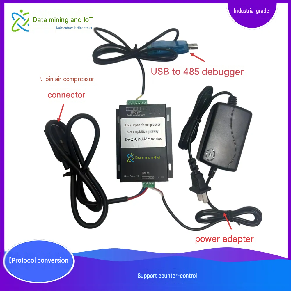
The DAQ-GP-AMmodbus series air compressor protocol conversion gateway is a gateway device from Shanghai Daq IoT Technology Co., Ltd. for compressor data acquisition, protocol conversion and reverse control. It enables remote monitoring of mainstream air compressors and lets compressor data flow quickly into third-party systems such as PLCs or DCS.
The gateway monitors compressor operating status and parameters, and can control compressor start, stop, load and unload over a serial connection. No extra configuration is needed to connect 5 Atlas Copco, Ingersoll Rand or other compressors at the same time (up to 10), forming a compressor group control network. Host system software or a PLC connects to this network in real time through the RS-485 interface using Modbus RTU.
3.2.1 Key Specifications
| Item | Specification |
|---|---|
| Model | DAQ-GP-AMmodbus (brand-specific models available on request) |
| Core functions | Compressor data acquisition, conversion of proprietary protocols to standard Modbus RTU, remote start/stop and load/unload reverse control, multi-device cluster access |
| Interfaces | MKLAN compressor-dedicated interface (DB9), A/B RS-485 Modbus interface |
| Power supply | 220 V AC, 60 mA |
| Dimensions | 122 × 84 × 24 (mm) |
| Operating environment | Temperature −30 °C to 75 °C, humidity 0–95% |
| Output protocol | RS-485 Modbus RTU (standard), read by host system, PLC or wireless terminal |
| Accessories | Power adapter, compressor communication connector |
3.2.2 Gateway Selection Guide
| Model | Description |
|---|---|
| DAQ-GP-AMmodbus-Atlas | Connects to Atlas Copco MK2, MK4 and MK5 computer controllers |
| DAQ-GP-AMmodbus-Ingersoll | Connects to Ingersoll Rand compressors |
| DAQ-GP-AMmodbus-XX | Other compressor brands, such as Sullair, Fusheng, Kaishan and Kobelco |
| …… | Custom (dedicated gateway models developed for non-standard controller protocols) |
3.2.3 Product Features
● Electrical: 220 V AC, 60 mA power supply, matched to industrial site power.
● Communication: standard RS-485 Modbus RTU output; the host system, PLC or wireless terminal reads data using Modbus slave addresses 1–10. The MKLAN interface connects one-to-many to compressor controllers, and the A/B terminals are the Modbus (485) interface.
● Mechanical: 122 × 84 × 24 (mm), DIN-rail or wall mounting, compact design.
● Operating environment: −30 °C to 75 °C, 0–95% humidity, suited to a wide range of industrial sites.
● Capability limits: the gateway itself only outputs Modbus RTU and does not support 4G or MQTT wireless reporting directly. Wireless reporting and cloud platform integration are provided by the matching wireless communication management unit or intelligent terminal (see Section 3.3).
3.3 Wireless Communication Management Unit / Wireless Intelligent Terminal
When site data must be reported to a public cloud platform or a remote monitoring center, add a matching wireless communication management unit or wireless intelligent terminal on the uplink side of the protocol conversion gateway. As the core hardware of the data reporting layer, this device collects the Modbus RTU data output by the gateway and reports it over 4G or Ethernet to any public server or cloud platform using MQTT, TCP, UDP, HTTP and other protocols.
3.3.1 Key Specifications
| Item | Specification |
|---|---|
| Device type | Industrial-grade wireless communication management unit / wireless intelligent terminal |
| Core functions | Modbus RTU data acquisition, protocol encapsulation, 4G or Ethernet wireless reporting, cloud platform integration, breakpoint resume |
| Downlink acquisition interface | RS-485 Modbus RTU master, can poll data from multiple protocol conversion gateways |
| Uplink communication | 4G LTE full network / Ethernet (RJ45) |
| Supported protocols | MQTT, TCP, UDP, HTTP, SSL; other protocols on request |
| Data forwarding | Any public server or cloud platform |
| Power supply | 220 V AC or wide-range DC |
| Operating environment | Industrial grade, −30 °C to 75 °C, suited to all types of industrial sites |
3.3.2 Functional Features
● Data acquisition: acts as a Modbus RTU master, polling compressor data from the protocol conversion gateway by slave address 1–10, then reporting it as one aggregated stream.
● Wireless uplink: 4G LTE full network and Ethernet uplink, for sites with or without network coverage.
● Multi-protocol reporting: MQTT, TCP, UDP, HTTP and SSL reporting, connecting to any public server and mainstream cloud platforms.
● Breakpoint resume: local data caching with breakpoint resume, so no data is lost during a network outage and is automatically re-sent once the link recovers.
● Platform integration: customized platform integration, including Alibaba Cloud IoT Platform, China Mobile OneNet and Huawei Cloud (see Section 6).
3.4 On-Site Installation
● Location: the protocol conversion gateway is installed near the compressor control cabinet, and the wireless communication management unit or intelligent terminal near the gateway or inside the low-voltage cabinet. Both use DIN-rail or wall mounting, with good ventilation and away from strong electromagnetic interference.
● Network topology: compressor controllers are daisy-chained into the MKLAN interface of the gateway; the A/B terminals of the gateway connect over RS-485 to the wireless communication management unit or intelligent terminal; the wireless terminal reports to the cloud platform or local industrial PC over 4G or Ethernet.
● Address configuration: each compressor controller is given a unique address (1–10), mapping to Modbus slave addresses 1–10 on the gateway. The wireless terminal uses these addresses to distinguish devices.
Standard installation procedure:
- Switch off power to the compressor controller and confirm there is no risk of live working.
- Plug the DB9 connector into the “LAN” socket of the compressor controller and connect the controller communication port to the MKLAN interface of the protocol conversion gateway with the dedicated communication cable.
- Connect the gateway to 220 V AC power and confirm the power indicator lights up.
- Set the address on the compressor controller panel to 1–10 so that it matches the Modbus slave address mapping of the gateway.
- Connect the A/B terminals of the gateway over RS-485 to the RS-485 acquisition port of the wireless communication management unit or intelligent terminal (or directly to the local industrial PC or PLC).
- Power up the wireless communication management unit or intelligent terminal and configure the 4G or Ethernet and reporting platform parameters.
- Test the end-to-end data link: compressor → gateway → wireless terminal → cloud platform, and confirm data is acquired and reported correctly.
3.5 Wiring
3.5.1 Terminal Assignments
| Device | Terminal / interface | Function | Wiring rules |
|---|---|---|---|
| Protocol conversion gateway | MKLAN interface | Communication interface for the compressor controller, DB9 connector | Standard DB9 male connector, mates with the LAN or communication port of the compressor controller; supports one-to-one or daisy-chain connection |
| Protocol conversion gateway | A/B terminals | Modbus RTU output to wireless terminal, host system or PLC | A to RS-485+, B to RS-485−, GND to shielded ground; communication distance ≤ 1200 m |
| Protocol conversion gateway | Power terminals | 220 V AC power input | L to live, N to neutral, PE to protective earth; ensure reliable grounding |
| Wireless communication management unit / intelligent terminal | RS-485 acquisition port | Downlink acquisition of gateway Modbus RTU data | A/B to the gateway A/B terminals, common GND |
| Wireless communication management unit / intelligent terminal | 4G antenna / Ethernet port | Uplink wireless reporting | Connect the 4G antenna or RJ45 cable and access the internet |
| Wireless communication management unit / intelligent terminal | Power terminals | Device power supply | Connect 220 V AC or wide-range DC according to device specification |
3.5.2 Typical Wiring Topology
Single compressor wiring (with wireless reporting): compressor controller communication port → gateway MKLAN interface → gateway A/B terminals → RS-485 port of the wireless communication management unit or intelligent terminal → 4G or Ethernet → cloud platform or host system software (Atlas Copco compressor shown as an example).
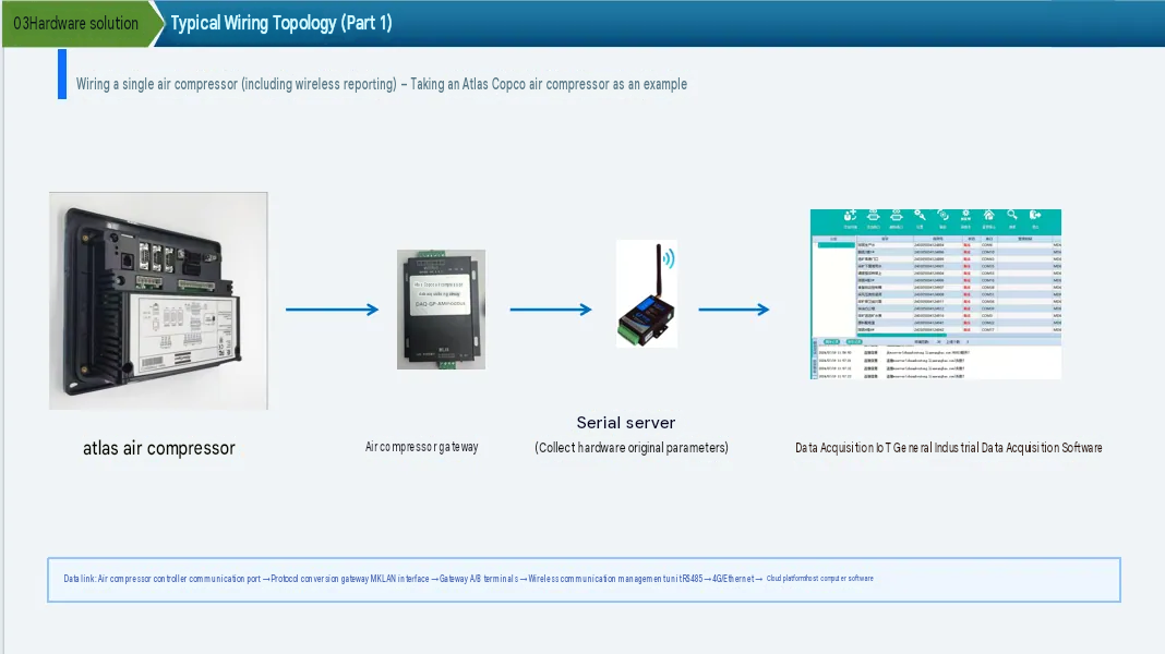
[Figure 1: Atlas Copco air compressor data acquisition and wireless reporting]
Multi-compressor cluster wiring: compressor No. 1 controller communication port → compressor No. 2 controller communication port → …… → gateway MKLAN interface → gateway A/B terminals → wireless communication management unit or intelligent terminal → 4G or Ethernet → cloud platform or industrial PC. Multiple AC compressors form a daisy-chain network that connects to the MKLAN interface of the DAQ-GP-AMmodbus gateway. The gateway then sends Modbus RTU data over RS-485 to the wireless communication management unit or intelligent terminal, which performs the wireless reporting.
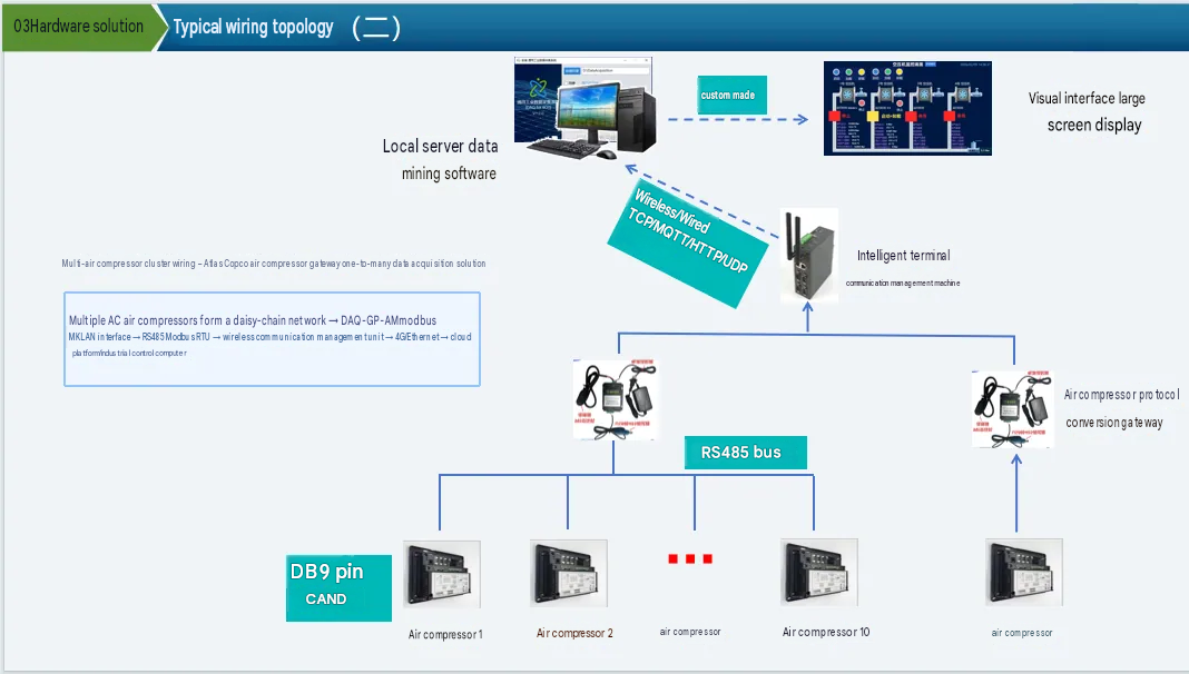
[Figure 2: Atlas Copco air compressor one-to-many data acquisition]
3.5.3 Wiring Precautions
● Use shielded twisted-pair cable for communication, with the shield grounded at one end only to avoid ground loops.
● Route communication cable separately from power cable, with a spacing of ≥ 30 cm to avoid electromagnetic interference.
● When several devices are chained, fit 120 Ω terminating resistors at both ends of the bus to improve communication stability.
● After wiring, check that all terminals are tight, with no looseness or short circuits.
● A CAN bus must not exceed 80 m; beyond this length the signal attenuates.
4. Software Functions
The air compressor monitoring platform supplied with this solution uses a layered design: data acquisition layer, data storage layer and application layer. Core functions are as follows.
4.1 Data Acquisition and Storage
● Second-level real-time acquisition: all core compressor operating parameters are acquired in real time, at up to 1 s per sample. Core parameters include:
Operating status: running/stopped, loaded/unloaded, manual/auto mode, local/remote control;
Process parameters: discharge pressure, discharge temperature, oil temperature, oil pressure, oil separator differential pressure, cooler pressure;
Equipment operating data: running hours, loaded hours, starts, load cycles, motor speed;
Alarm and fault information: general alarm, fault shutdown, emergency stop, motor overload, maintenance reminder;
Control commands: remote start/stop, load/unload, pressure upper and lower limit settings and other reverse control operations.
● Data storage: dual storage in local and cloud databases, with traceable history and a configurable retention period of up to 5 years or more.
● Protocol adaptation: a built-in protocol library for all compressor brands, so devices connect without secondary development; custom development is available for non-standard protocols.
4.2 Centralized Monitoring and Visualization
● Fleet status overview: a dashboard shows the running/stopped/fault status of every compressor, with total devices, online devices, running devices and faulted devices at a glance.
● Real-time data board: the detail page of each device groups all real-time operating parameters, highlights out-of-limit values in red, and offers a configurable refresh rate.
● SCADA visualization: customized process flow diagrams mirror the actual compressor sequence and show operating status directly.
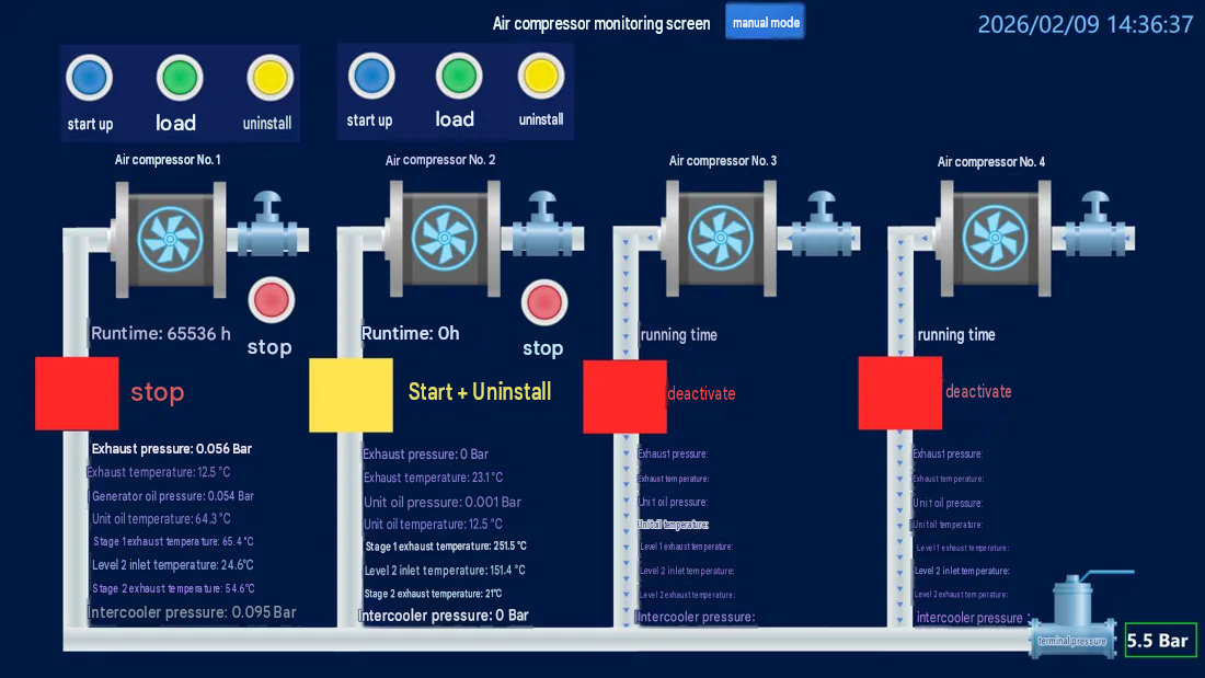
[Figure 3: Customized dashboard interface]
4.3 Intelligent Group Control and Automation
● Automatic rotation: rotation strategies can be set for multiple compressors, for example running in turn every 6 hours, to balance wear and extend the service life of the fleet.
● On-demand start/stop: compressors start and stop automatically based on network pressure. When network pressure falls below the lower limit, a standby machine starts to top up; once target pressure is reached, the standby machine stops, saving energy.
● Automatic fault isolation: when a running machine faults, the system removes it from the running queue and switches seamlessly to a standby machine, so air supply is not interrupted.
● Flexible control modes: manual and automatic modes switch seamlessly. In manual mode, each machine can be started, stopped, loaded and unloaded individually for special operating conditions.
● Configurable group control parameters: rotation interval, pressure limits, device priority and other parameters are all configurable for different site conditions.
4.4 Alarms and Early Warning
● Real-time alarm push: out-of-limit parameters, faults and shutdowns trigger an alarm immediately, delivered by pop-up, audible alert, SMS or WeChat push.
● Alarm severity levels: alarm levels are configurable, classified by urgency as general warning, major alarm and critical fault, each with its own push strategy.
● Alarm history: all alarm records are stored in full, including time, content, level and handling status, with alarm statistics and analysis.
● Preventive maintenance alerts: maintenance reminders are triggered automatically from running hours and operating status, with a configurable service interval, turning repair-after-failure into warning-based maintenance.
4.5 Energy Efficiency Analysis and Reports
● Energy efficiency analysis: based on historical operating data, the system analyzes unloaded rate, loaded rate and specific power per unit of air output to identify savings potential and optimize operating strategy.
● Operating reports: daily, weekly and monthly reports are generated automatically, covering running hours, loaded hours, start/stop counts and energy data, exportable to Excel or PDF.
● Data traceability: historical trend curves can be queried by time range and parameter type for fault analysis and operating optimization.
● Third-party integration: connects to existing PLC, DCS, MES and ERP systems, with standard Modbus RTU output for data exchange.
5. Acquisition Parameters and Modbus Address Table
The protocol conversion gateway exposes a standard register address table to the host system or wireless communication management unit over Modbus RTU, covering control commands, process parameters, digital inputs, operating status, runtime statistics and pressure band settings. The host system, PLC or wireless terminal accesses the corresponding compressor by Modbus slave address 1–10, and the same address table applies to all. Specific register addresses are defined in the point list document delivered with the gateway. Core acquisition parameters are described below.
5.1 Control Commands
| No. | Parameter | Access | Description |
|---|---|---|---|
| 1 | Control command | RW | 1: start; 2: stop; 3: load; 4: unload |
| 2 | Reset command | R | 1: fault shutdown; 2: start fault |
5.2 Process Parameters (Pressure)
Pressure parameters are Int16 in Bar; actual value = read value × 0.001.
| No. | Parameter | Data type | Description |
|---|---|---|---|
| 3 | Discharge pressure | Int16 | Unit Bar, value × 0.001 |
| 4 | Oil separator differential pressure | Int16 | As above |
| 5 | Oil pressure | Int16 | As above |
| 6 | Intercooler pressure | Int16 | As above |
5.3 Process Parameters (Temperature)
Temperature parameters are in °C; actual value = read value × 0.1.
| No. | Parameter | Data type | Description |
|---|---|---|---|
| 7 | Discharge temperature | Int16 | Unit °C, value × 0.1 |
| 8 | No. 1 rotor discharge temperature | Int16 | As above |
| 9 | No. 2 rotor inlet temperature | Int16 | As above |
| 10 | No. 2 rotor discharge temperature | Int16 | As above |
| 11–13 | Reserved | Int16 | Reserved for expansion (value × 0.1) |
| 14 | Oil temperature | Int16 | Unit °C, value × 0.1 |
5.4 Digital Inputs
| No. | Parameter | Description |
|---|---|---|
| 15 | Emergency stop input | 0: emergency stop; 1: normal |
| 16 | Remote start/stop input | 0: stop; 1: start |
| 17 | Remote load/unload input | 0: unload; 1: load |
| 18 | Remote pressure control input | 0: local; 1: remote |
| 19 | Main motor overload | 0: overload; 1: normal |
| 20 | Fan motor overload | 0: overload; 1: normal |
| 21 | Motor running feedback | 0: stopped; 1: running |
5.5 Operating Status
| No. | Parameter | Description |
|---|---|---|
| 22 | Operating status | 1: running; 0: stopped |
| 23 | Load status | 1: loaded; 0: unloaded |
| 24 | General alarm | 1: alarm; 0: normal |
| 25 | General fault shutdown alarm | 1: alarm; 0: normal |
| 26 | General fault shutdown | 1: shutdown; 0: normal |
| 27 | Maintenance reminder | 1: service due; 0: normal |
| 28 | Start fault | 1: fault; 0: normal |
| 29 | Emergency stop | 1: emergency stop; 0: normal |
| 30 | Manual/auto regulation | 1: auto; 0: manual |
| 31 | Local/remote control | 1: remote; 0: local |
5.6 Runtime Statistics
The following parameters use 32-bit double-word storage; actual value = high word × 65536 + low word.
| No. | Parameter | Access | Description |
|---|---|---|---|
| 32 | Running hours (high + low) | R | High word × 65536 + low word, in hours |
| 33 | Loaded hours (high + low) | R | High word × 65536 + low word |
| 34 | Motor starts (high + low) | R | High word × 65536 + low word |
| 35 | Module communication time (high + low) | R | High word × 65536 + low word |
| 36 | Load cycles (high + low) | R | High word × 65536 + low word |
5.7 Pressure Band Settings
| No. | Parameter | Description |
|---|---|---|
| 37 | Pressure band selection | 1 or 2 |
| 38 | Load pressure band 1 | Unit Bar, value × 0.001 |
| 39 | Unload pressure band 1 | As above |
| 40 | Load pressure band 2 | As above |
| 41 | Unload pressure band 2 | As above |
Note: the point table above covers the common acquisition points of mainstream compressors such as Atlas Copco. Register addresses for other brands and controller models are defined in the protocol document delivered with the gateway. Custom development is available for non-standard protocols.
6. Project Case Study
Project: Atlas air compressor cluster intelligent group control and data visualization system. Date: January 2026.
6.1 Background and Pain Points
The customer plant runs 4 ATLAS compressors (2 in service at the time, 2 more added later) that supply stable air to the production line. Before the upgrade the plant faced the following issues:
● Each compressor ran independently, and operating parameters (pressure, temperature and so on) were recorded by manual inspection rounds. Data was scattered and could not be monitored centrally.
● Start/stop and rotation depended on manual action, with the risk of missed switching and uneven load, which affected equipment life.
● When one machine faulted, the operating strategy could not be adjusted automatically in time, which could affect air supply to production.
● There was no historical data for traceability, so energy efficiency analysis and preventive maintenance were difficult.
6.2 Objectives and Customized Requirements
The customer wanted a centralized monitoring and intelligent group control system with the following functions:
● Centralized data visualization: real-time status of each unit, including running hours, inlet and outlet temperature of the low-pressure and high-pressure hosts, inlet and outlet pressure, oil pressure and oil temperature, acquired in real time from the controllers and displayed together on a single dashboard.
● Intelligent rotation control: automatic sequential rotation of the 4 units, each running in turn for 6 hours (configurable), with one unit running and the other three off, to balance wear and extend overall service life. The rotation interval is configurable.
● On-demand intelligent start/stop: compressors start and stop automatically based on network pressure. When terminal pressure falls below the configured lower limit (pressure is configurable), a standby machine starts to top up. Once target pressure is reached, the original host keeps running and the standby machine stops. If the host faults and shuts down, it is removed automatically and the remaining units continue in automatic sequence, saving energy.
● High availability: if a running host faults, the system must isolate it safely from the running queue and bring a standby unit online automatically, so air supply is not interrupted.
● Flexible control modes: manual control is retained and can be switched between “auto” and “manual”. Both the upper and lower pressure limits are configurable to cover special operating needs.
6.3 Solution
The customer received a customized integrated hardware and software solution built on “protocol conversion gateway + wireless communication management unit / intelligent terminal + in-house data acquisition platform + SCADA visualization software”:
(1) Hardware integration layer
Atlas Copco protocol conversion gateways (DAQ-GP-AMmodbus) communicate reliably with each compressor controller over standard Modbus RTU. The gateway connects to the compressor panel through the DB9 compressor interface for one-to-many data acquisition, protocol conversion and initial data processing, and outputs the data over Modbus RTU for the local data acquisition system and the wireless communication management unit or intelligent terminal to read and report.
(2) Data and logic core layer
An in-house general-purpose industrial data acquisition system is deployed to parse the device point list precisely and acquire and store all compressor parameters in real time at second-level intervals (multiple database types supported). A purpose-built group control logic engine inside the system reliably executes the core strategies: automatic rotation, on-demand start/stop and removal of faulted devices, keeping the logic stable and accurate.
(3) Application layer
A customized industrial SCADA dashboard was built for the customer, with an intuitive design that includes:
● Device status overview: running/stopped/fault status of the four units at a glance.
● Real-time data panel: all key temperature and pressure parameters in one place.
● Intelligent group control panel: set the rotation interval and pressure limits, and view the current host and queue order.
● Manual control panel: individual start/stop buttons for each device and a manual/auto mode switch.
● Historical trend curves: trends of key parameters on demand, for fault analysis and energy management.
● Automatic alarm system: alarm messages pop up and are logged when a device behaves abnormally.
6.4 Results
● Visible management: shift staff see the status of every compressor at the industrial PC, replacing manual inspection and meter reading, with higher management efficiency.
● Automated control: fully automatic rotation and on-demand start/stop remove human error, balance equipment utilization and extend overall service life.
● Energy-efficient operation: precise on-demand start/stop avoids pointless running and delivers clear energy savings.
● High availability: fast isolation of faulted devices and seamless takeover by standby units greatly improve air supply stability and reduce unplanned downtime risk.
● Digital maintenance: complete operating history gives preventive maintenance a precise data basis, turning repair-after-failure into warning-based maintenance.
7. Application Value and Benefits
The solution has been deployed and proven at sites in several industries, with clear overall benefits. Core value is summarized in the table below:
| Value dimension | Pain point before upgrade | What the solution provides | Expected benefit |
|---|---|---|---|
| Management efficiency | Manual inspection and meter reading, scattered data, no central view of device status | SCADA dashboard with centralized visualization of all plant compressors in real time | Significantly higher management efficiency, no manual meter reading |
| Equipment life | Start/stop and rotation depend on manual action, uneven load, unbalanced wear | Automatic sequential rotation, balanced running hours, automatic isolation of faulted devices | More even equipment utilization, longer overall service life |
| Energy savings | Pointless running, air supply mismatched to demand, high energy consumption | On-demand intelligent start/stop, precise network pressure control, no unloaded waste | Clear energy savings, lower specific power per unit of air |
| Operating stability | Faults cannot be corrected in time, affecting air supply to production | Automatic fault isolation plus seamless standby takeover, high availability | Less unplanned downtime risk, stable air supply |
| Maintenance approach | Repair after failure, no data support, reactive maintenance | Complete operating history stored, preventive maintenance reminders triggered | Repair-after-failure becomes warning-based maintenance |
| Data assets | No historical traceability, energy analysis not possible | History traceable for 5 years or more, energy analysis and reports supported | Data-driven operating optimization and decisions |
| System integration | Data silos between systems, difficult interconnection | Standard Modbus RTU output plus multi-protocol reporting from the wireless terminal, connecting to PLC, DCS and cloud platforms | Data exchange across systems, supporting digital transformation |
8. About Us
Shanghai Daq IoT Technology Co., Ltd. is a specialist provider in industrial data acquisition, focused on developing and delivering data acquisition, protocol conversion, centralized monitoring and intelligent group control solutions for air compressors and other industrial equipment. With the mission of “making every industrial device intelligent and controllable”, the company has developed a series of air compressor protocol conversion acquisition gateways, wireless communication management units / intelligent terminals and a general-purpose industrial data acquisition platform. The protocol library now covers more than 190 controller models across mainstream domestic and imported compressor, centrifugal compressor and auxiliary equipment brands.
Our commitment: what you buy is not only a product, but attentive and thorough technical support. On site, the protocol conversion gateway only needs a general technician to wire and power it up; no commissioning is required. We provide remote guidance and remote configuration free of charge, and send data to the cloud platform you specify. As an industrial data acquisition expert, Daq IoT also provides free IoT solution consulting.
8.1 Contact
| Item | Information |
|---|---|
| Company | Shanghai Daq IoT Technology Co., Ltd. |
| Telephone | |
| business@daq-iot.com | |
| Website |
8.2 Service Commitment
● Simple on-site delivery: basic installation only, no technician visit required, with remote commissioning throughout, for easier delivery.
● Free remote service: remote guidance and remote configuration at no charge, with data sent to the cloud platform you specify.
● Free solution consulting: as an industrial data acquisition expert, Daq IoT provides free IoT solution consulting.
● Continuous technical support: new models are adapted continuously, custom development is available for non-standard protocols, and technical support covers the whole lifecycle.
End of document
Shanghai Daq IoT Technology Co., Ltd. | Industrial Data Acquisition Expert
Copyright in this solution belongs to Shanghai Daq IoT Technology Co., Ltd. Reproduction without permission is prohibited.