
How Do You Monitor the Energy Use and Operating Status of Electrical Equipment?
A One-Stop Wireless Data Acquisition Solution
In facility management and plant maintenance, distributed electrical loads are widely scattered and hard to supervise on site. Manual rounds consume time and labor and still cannot deliver all-hour, full-coverage supervision. Based on a live deployment, this solution uses 4G wireless transmission to monitor the power use of pollution control equipment. It needs no complex cabling, collects energy data and determines operating status quickly, and connects to third-party data platforms — a practical reference for intelligent management of pollution control equipment.
1. Background and Requirements
The deployment covers several townships in Xinxiang City, Henan — Weihui, Huixian, Changyuan and Yuanyang — with more than 40 monitoring points at wastewater treatment facilities. Management needs for such distributed pollution control equipment come down to two things: knowing precisely whether each unit is actually running, so that equipment is not left idle; and collecting power data in real time and summarizing it, which replaces manual site visits, cuts management cost and improves supervision.
The limits of the traditional approach are clear. Manual inspection means repeated trips between points, with high labor and material cost. It cannot provide 24/7 monitoring, so gaps in supervision remain. Some units have no meter at all, making status hard to judge from data. A low-cost, easy-to-deploy wireless acquisition solution with stable data transmission is therefore needed for distributed equipment.
2. Core Acquisition Device and Specifications
The SC-GP-EM4G wireless power monitor is the core acquisition device. Designed for power monitoring on industrial sites, it handles single-phase and three-phase equipment, needs no on-site cabling and can be added at the key power feed of a unit quickly, which makes it a practical choice for distributed monitoring.
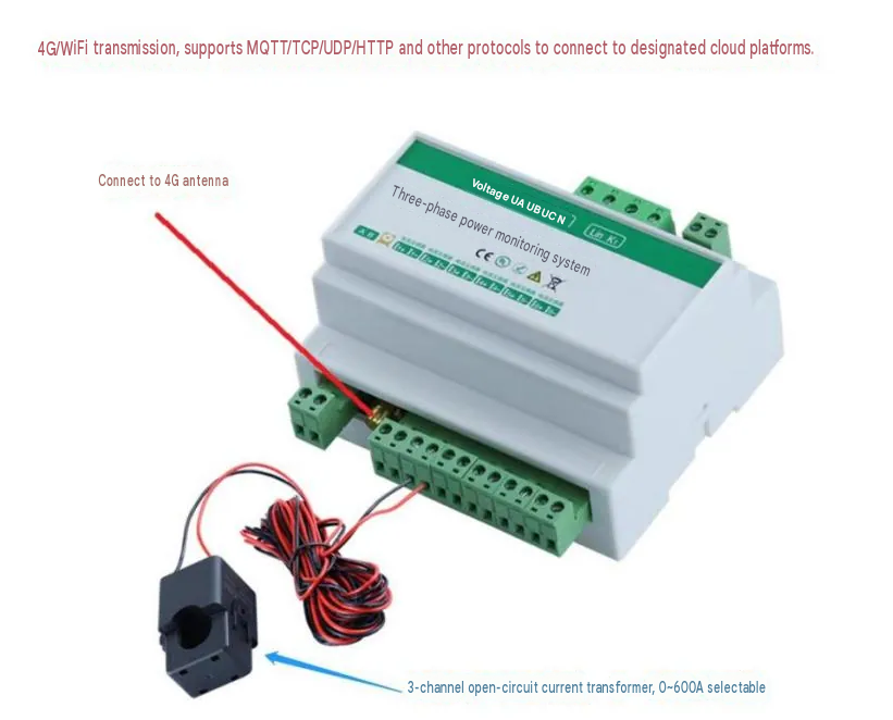
(1) Core functions
It collects line voltage and current in real time and calculates active power, apparent power, power factor and active energy, reproducing the equipment’s power use completely.
It transmits over 4G or WiFi, uploading data directly to the cloud platform for remote viewing.
It supports unmanned monitoring: with a relay it cuts power automatically on overvoltage or overcurrent, protecting the equipment.
The default reporting interval is 5 minutes and can be changed remotely to suit different monitoring needs.
(2) Key Parameters
Acquisition channels: 6 AC current and voltage channels, sampling interval 1 s per channel, response time ≤100 ms, so data is timely.
Measurement range: voltage 100 V–400 V, current 0–100 A by default. Accuracy: voltage 0.5% rdg., current 2% rdg.
Current transformers: 2000:1 by default, 0–600 A ranges available, 6 split-core CTs for easy installation.
Protocols: MQTT, TCP, UDP and HTTP are supported, allowing connection to a designated cloud platform.
(3) Where the Device Fits
The device suits power monitoring of pollution control equipment, status monitoring of distributed plant loads and energy accounting for electrical facilities. It is particularly appropriate where there is no meter, points are scattered and cabling is impractical.
3. Implementation Steps
(1) Preliminary Site Survey
Record the equipment type at each point and confirm whether the load is single-phase or three-phase. Survey cable gauge and current range to establish the CT bore (16 mm, 24 mm) and range (0–100 A) required.
Choose the installation position, preferably at the main breaker of the monitored equipment, confirm space for the CTs and the acquisition unit and leave room to work.
Test 4G signal strength at each point, paying attention to underground distribution boxes and sealed steel enclosures, and prepare extension antennas in advance.
Confirm the power available on site. This solution relies on a three-phase 220 V / 380 V AC supply, so the feed to the device is planned beforehand.
(2) On-Site Installation
Installation must be carried out by qualified electricians in line with electrical safety rules.
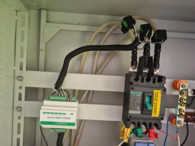
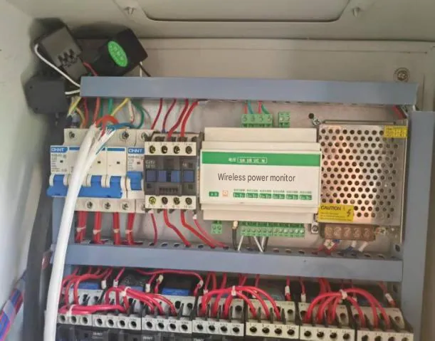
Current transformers: clamp the split-core CTs directly onto the three-phase circuit of the monitored equipment. No wiring needs to be disconnected and installation is quick.
Voltage wiring: connect the device voltage terminals to the site circuits and insulate every connection.
Unit and antenna: fix the acquisition unit in a suitable position inside the distribution box. Where 4G signal is weak, run the antenna on an extension cable to a position outside the box with good reception.
Power-up: connect the supply, check the wiring and switch on, confirming that the device starts normally.
(3) Remote Configuration and Data Integration
Technicians configure device parameters remotely, including acquisition interval, transmission protocol and platform address.
The device is commissioned against the cloud platform and data transmission is verified, confirming that voltage, current and power upload in real time.
Where a third-party platform is involved, the data format is adapted to its protocol so reporting and synchronization run automatically without manual work.
(4) Installation Precautions
CT bore and range must match the site circuit exactly; a mismatch introduces measurement error.
All wiring must be done with the power off, and connections must be checked carefully afterwards to prevent short circuits or reversed polarity.
When an antenna is fitted through a sealed enclosure, the entry must be sealed against dust and moisture that would affect operation.
After installation, run the system for 24 hours to check data transmission and acquisition accuracy, and adjust as needed.
4. Platform Functions
(1) Real-Time Data Monitoring
The cloud platform shows live power data for every monitoring point — voltage, current, power and energy. Each device carries a unique ID so points can be located precisely, and data refreshes in real time, so staff see the status of all distributed equipment from the back office without visiting site.
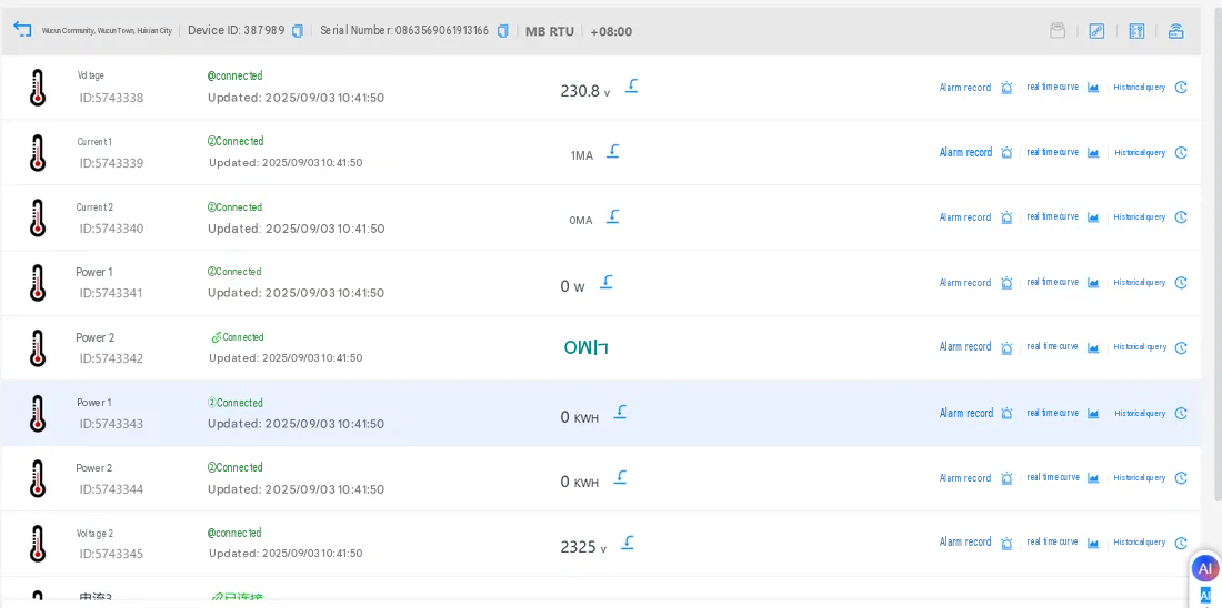
(2) Determining Operating Status
Analyzing changes in power data establishes the actual operating status. If a unit shows no current or power during its normal working hours, it has not started. Abnormal fluctuations reveal a developing fault. Comparing energy figures over time also shows the load the equipment is carrying.
(3) Historical Data Management and Analysis
The platform stores historical power data automatically and supports queries by hour, day or month, generating live curves and energy trend charts. Maximum, minimum and average values are calculated automatically, supporting energy analysis and maintenance planning.
(4) Third-Party Platform Integration
Collected data connects to third-party data platforms over standard protocols and reports automatically, on an hourly, daily or other scheduled basis. The data format matches platform requirements, so no manual entry is needed and reporting stays timely and consistent.
(5) Management Efficiency
Once deployed, the solution fully replaces manual rounds with 24/7, full-coverage monitoring of distributed pollution control equipment. One person can manage dozens of monitoring points, labor and material costs fall sharply and supervision efficiency improves by more than 80%.
5. Summary and Extended Applications
(1) Core Advantages
Easy to deploy: wireless transmission, no site cabling, split-core CTs that clamp on, and a short installation time per point — suited to fast roll-out across distributed points.
Low cost: compared with wired monitoring, most cabling and construction cost is avoided, and maintenance is inexpensive.
High reliability: multiple levels of power protection suit complex industrial environments, 4G transmission is stable and an external antenna covers weak-signal areas so the data link is not interrupted.
Wide fit: multi-protocol integration works with a range of cloud and third-party data platforms, single-phase and three-phase equipment are both supported, and units without meters can still be measured accurately.
Intelligent: data is collected, uploaded and analyzed automatically, so staff see equipment status remotely and management moves from manual to intelligent.
(2) Extended Applications
Beyond wastewater treatment in townships, the solution applies to waste gas treatment equipment in industrial parks, distributed production equipment in factories and outdoor water facilities — any distributed load without a meter that is impractical to cable and needs energy accounting and status monitoring. It offers a repeatable, practical model for intelligent facility management.
(3) Maintenance Recommendations
Inspect acquisition devices remotely at intervals, checking online status and data transmission and resolving offline devices and data anomalies promptly.
Check the equipment on site every six months, focusing on wiring, CTs and antenna mounting, and clean dust from device surfaces to keep it running properly.
Adjust the acquisition interval and reporting rules as management needs change, and refine platform display and analysis to improve the level of detail in management.
Note
All installation and wiring must be carried out by personnel with electrical qualifications, in strict compliance with on-site electrical safety rules, to avoid electrical accidents. Device selection should follow the actual site environment and monitoring requirements, with survey and matching completed in advance so the solution performs as intended.