
Solar energy is now used widely across the energy sector. The solar charge controller (MPPT) is one of the core components of a PV system, and data acquisition from it is essential for monitoring, optimization and management. This acquisition approach for MPPT controllers covers hardware connection, use of the communication interfaces and data handling, and delivers efficient monitoring and management of the PV system.
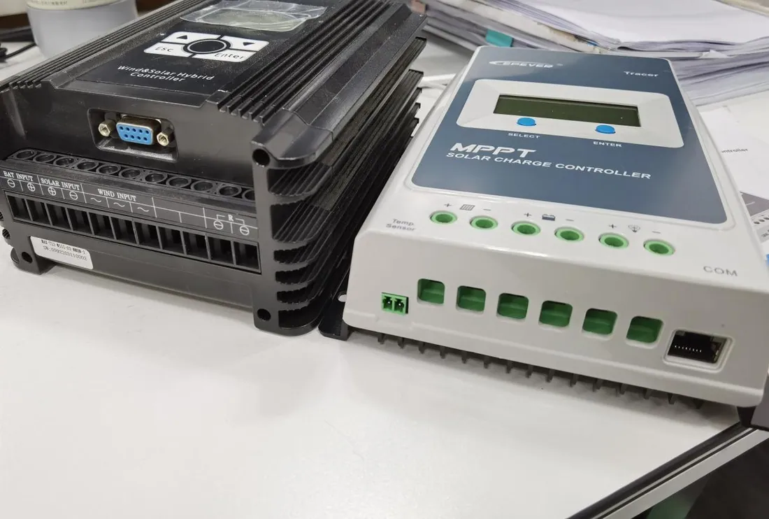
1. Hardware Configuration and Connection
MPPT Controller
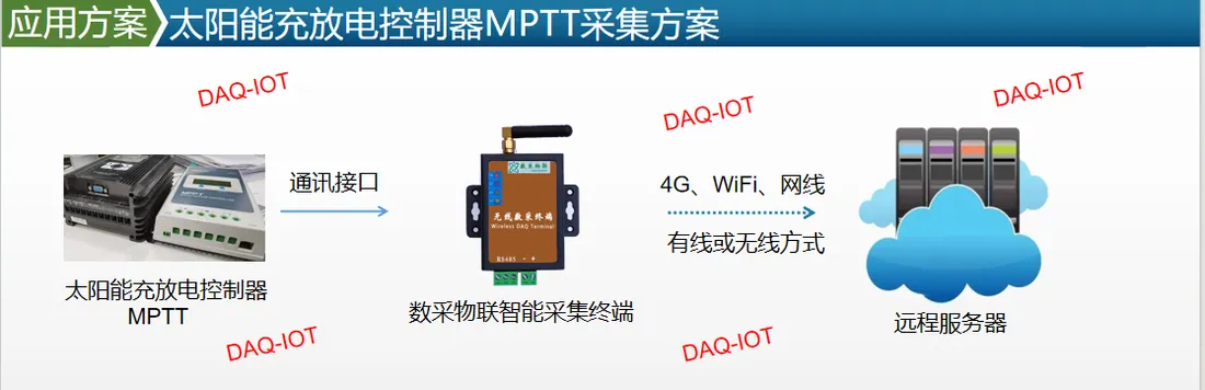
As shown in the figure above, an MPPT controller usually has a compact enclosure and a rich set of functional interfaces. Its display shows key parameters such as voltage and current in real time, giving on-site operators information at a glance. The buttons on the controller are used for basic settings and for viewing parameters.
Cables connecting the PV panels, the battery and the load must be wired strictly according to the terminal markings on the controller, so that the electrical connection is correct and safe.
Acquisition Module
Select the acquisition module according to actual needs. For wired acquisition, choose a module with an Ethernet uplink output and connect it to the RS-485 port of the MPPT controller with twisted pair; data is then carried to the back-end system over the Ethernet uplink. This connection has strong noise immunity and suits industrial environments and other scenarios with high requirements for data stability.
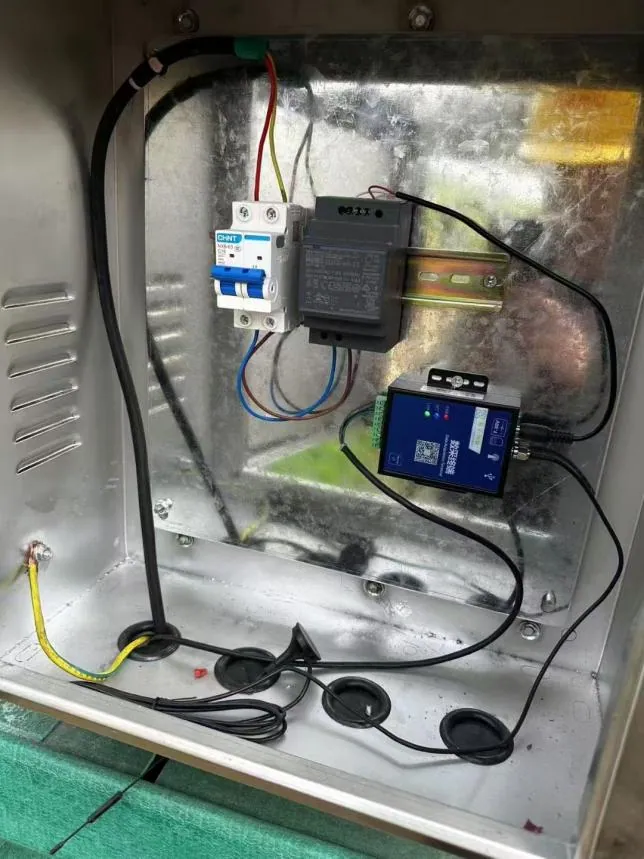
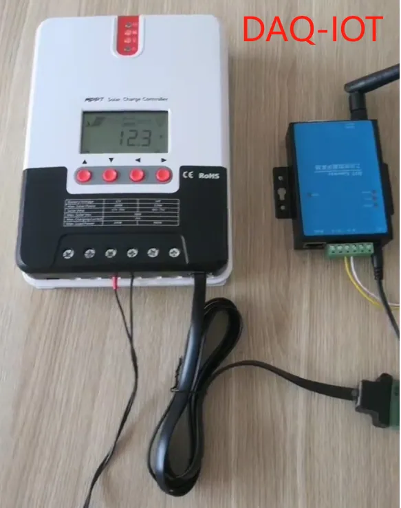
For wireless acquisition, use an acquisition module with wireless communication such as Wi-Fi, 4G or LoRa. Connect the module to the corresponding interface on the MPPT controller (a serial port, for example) and make sure the antenna is installed correctly to keep the wireless signal strong.
2. Communication Interfaces and Protocols
Hardware Communication Interfaces
RS-485 interface: the most common interface on MPPT controllers. It supports long transmission distances (hundreds of meters or even over a kilometer, depending on cable quality and ambient interference) and has strong noise immunity, which suits complex industrial environments. Twisted pair is normally used and effectively suppresses common-mode interference, keeping data transmission stable and reliable.
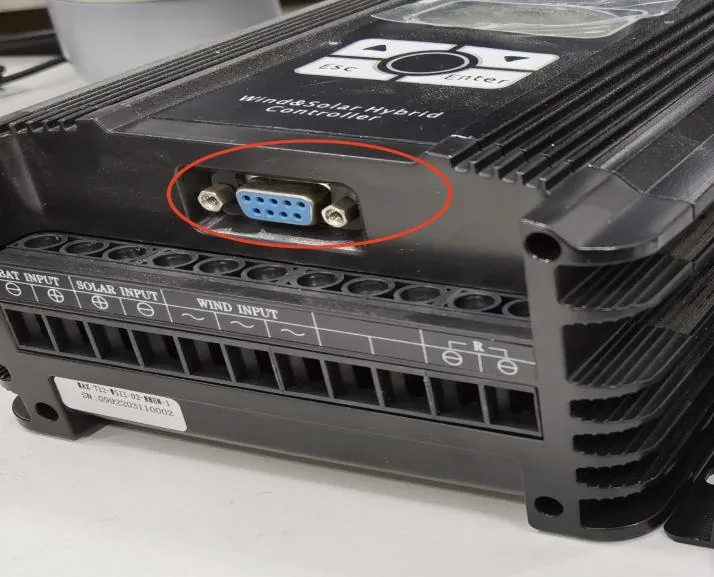
RS232 interface: another common interface. Its transmission distance is shorter, usually within about ten meters, and its noise immunity is somewhat weaker than RS-485. It is convenient where distance is not critical, such as short-range device connection and commissioning.
Ethernet interface (RJ45): as networking technology has developed, more and more MPPT controllers are fitted with an Ethernet port. Through this port the controller connects directly to a LAN or the internet for remote monitoring and data transmission. Ethernet offers high speed and good network compatibility and integrates easily with existing network infrastructure.
USB interface: mainly used to connect the controller to a local computer for parameter setting, firmware upgrades and data downloads. USB is plug-and-play, convenient to use, and fast enough for general data exchange.
Mainstream Communication Protocols
Modbus: a communication protocol widely used in industrial automation and also common in MPPT controllers. Modbus includes variants such as Modbus RTU (remote terminal unit) and Modbus TCP (Modbus over TCP/IP). Modbus RTU usually runs over serial ports such as RS-485 and RS232. Its data format is compact and transmission efficiency high, which suits applications with strict real-time requirements. It defines a set of function codes for reading and writing register data in the controller, such as voltage, current, temperature and status. Modbus TCP runs in Ethernet environments over the TCP/IP stack, with better network compatibility and scalability, which makes remote monitoring and multi-device networking easier.
CAN bus protocol: in PV systems with extremely high requirements for reliability and real-time performance, an MPPT controller may use CAN bus. CAN bus has a multi-master structure, error detection and automatic retransmission, and works reliably under severe electromagnetic interference, so data is transmitted accurately. It is used relatively rarely, mainly because hardware cost and development effort are higher, and Modbus already covers most communication needs in typical PV systems.
3. Data Acquisition and Processing
Data Acquisition Frequency
Set the acquisition frequency according to the importance of the system and its real-time requirements. For key parameters such as battery voltage and charge current, use a high frequency (once per second or per minute, for example) so that anomalies are found quickly. For parameters that change slowly, such as daily generation and cumulative charge, a lower frequency (once per hour or per day) reduces the load on data storage and transmission.
Data Processing and Storage
Acquired data must be processed and stored on the host system. First, run validity checks and discard outliers and bad data. Then format and store the data by category, either in a database (MySQL, SQL Server and so on) or in the file system (CSV, XML and so on), for later queries, analysis and reporting. Data processing software can also analyze the acquired data in real time, for example plotting voltage and current curves and calculating system efficiency, as a basis for system optimization and fault diagnosis.
4. Remote Monitoring and Management
Network Architecture
For remote monitoring and management, connect the acquisition system to the internet. A router or gateway on the LAN forwards data from the acquisition modules to a cloud server or a remote monitoring center.
The cloud server or remote monitoring center hosts the monitoring software and database, providing centralized management and monitoring of multiple PV systems. Users can reach the monitoring system from a web browser or a mobile app at any time to check system status, historical data and alarms.
Alarms and Notifications
The monitoring system must provide complete alarm functions. When acquired data crosses a preset threshold (battery overcharge or over-discharge, abnormal PV panel output, for example), the system raises an alarm and notifies the responsible staff by SMS, email or app push, so that action can be taken promptly and system faults and losses avoided.
This acquisition approach for solar charge controllers (MPPT) delivers comprehensive, efficient, real-time monitoring and management of a PV system. Whether acquisition is wired or wireless, combined with sensible data processing and remote monitoring it supports stable operation, optimized management and early fault warning, improves the reliability and economics of the PV system, and helps drive wider adoption of solar energy across the energy sector.
The implementation can be adjusted and optimized to suit the requirements and conditions of each project, so that it meets the acquisition needs of different PV system scenarios.