
Explosion-Proof Gauge Vision Recognition Solution for Oil, Gas and Chemical Plants
(Analog Dial Thermometers and Magnetic Flap Level Gauges)
Prepared by: Shanghai Daq IoT Technology Co., Ltd.
1 Project Overview
2 Target Instrument Recognition Analysis
3 Overall System Architecture
4 Hardware Selection and Explosion-Proof Requirements
5 Explosion-Proof Cabling Plan
6 Local Power Supply Plan
7 Local Recognition Software Deployment
8 Installation and Implementation Steps
9 Recommended Recognition Parameter Settings
10 Safety and Explosion-Proof Management
11 Risk Analysis and Countermeasures
12 Equipment List and Budget Reference
13 Summary
This solution targets flammable and explosive environments such as oil, gas and chemical plants. It covers two types of local instruments: analog dial thermometers (model example: WSS-485, range −30 °C to 100 °C) and magnetic flap level gauges. Explosion-proof scheduled-capture cameras plus local image recognition software provide non-contact automatic reading acquisition. While meeting explosion-proof safety requirements, the solution focuses on key implementation issues: camera power supply, signal transmission cable routing, local power tapping, and adaptation of the image recognition algorithm.
1.1 Project Background
Oil, gas and chemical plant areas contain many local indicating instruments. Traditional manual inspection readings have the following pain points: long inspection cycles, data that cannot enter DCS/SCADA/MES systems in real time, errors in manual transcription, and high personnel exposure risk in high-hazard areas. Deploying a vision recognition system in explosion-proof areas automatically converts local instrument readings into digital signals and feeds them into existing production information systems, enabling automatic data acquisition and remote monitoring.
1.2 Design Basis
Code for Design of Electrical Installations in Explosive Hazardous Environments, GB 50058
Explosive Atmospheres — Part 1: Equipment — General Requirements, GB 3836.1
Standard for Fire Protection Design of Petrochemical Enterprises, GB 50160
Code for Design of Instrument Piping and Wiring, HG/T 20512
Code for Design of Instrument Installation in Petrochemical Industry, SH/T 3104
Code for Design of Instrument System Grounding, HG/T 20513
1.3 Core Components of the Solution
Front-end acquisition: explosion-proof 4G/WiFi wireless scheduled-capture camera, with explosion-proof lens, fill light and mounting bracket
Network transmission: industrial explosion-proof router/switch, supporting wired or 4G wireless backhaul
Recognition software: Daq IoT instrument recognition software (deployed locally), supporting recognition of analog gauges and level gauges
Power supply system: local 220 V supply, converted by an explosion-proof distribution box to DC 12 V for the camera
Data application: recognition results connect to DCS, SCADA or MES through Modbus/database
2.1 Analog Dial Thermometers
The analog dial thermometers to be recognized on site are bimetal thermometers (model example: WSS-485). Their main features are as follows:
The dial is round, with a range of −30 °C to 100 °C, scale divisions of 2 °C or 5 °C, and accuracy class 1.5
A black pointer rotates from the dial center to indicate the current temperature; some dials have red/green warning color bands
The dial surface is glass or resin, with interference factors such as reflections, stains and water vapor
Mounting is mostly radial or axial, with the body connected to a pipe or equipment; the camera must shoot straight-on from above
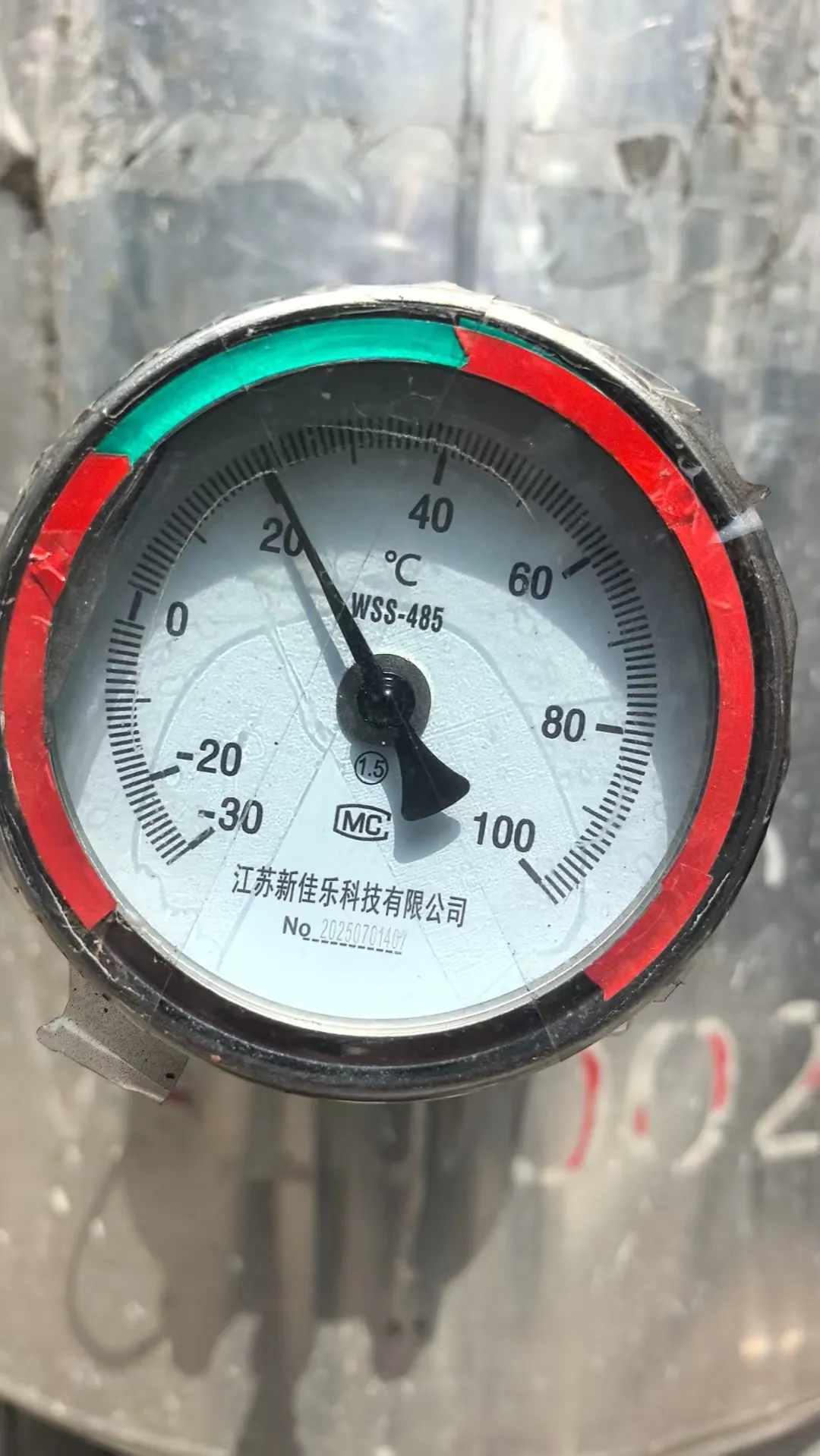
Recognition method: noise reduction, edge detection and transform detection are used to locate the pointer and scale marks. The angle between the line from the dial center to the pointer’s rotation center and the zero-scale line is calculated and converted into a temperature reading. The software supports automatic tilt correction for skewed dials and sub-region recognition, which effectively overcomes installation angle deviations.
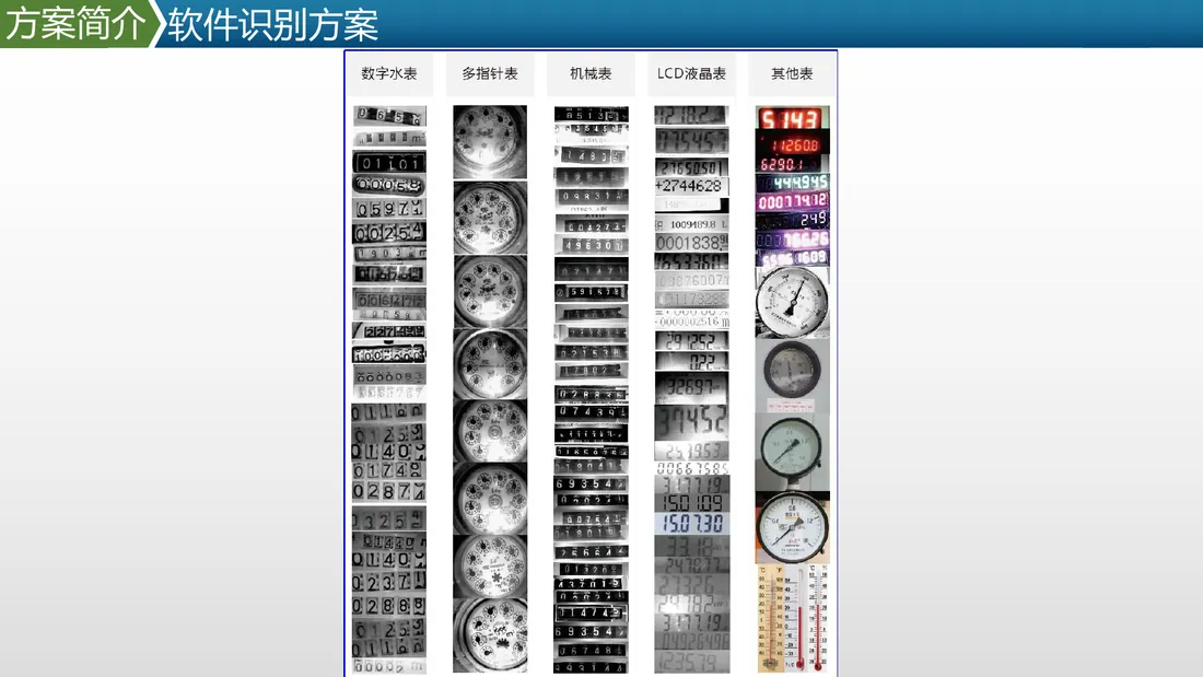
Figure 2-1 Examples of instrument types supported by the instrument recognition software (digital water meters, multi-pointer gauges, mechanical gauges, LCD gauges, etc.)
2.2 Magnetic Flap Level Gauges
A magnetic flap level gauge is a slender tubular instrument installed vertically. Its main features are as follows:
The main body is a stainless steel standpipe. An internal magnetic float rises and falls with the liquid level, and external flaps flip to show a red/white or yellow/white boundary
The range is usually 0 to several meters. A graduated scale is attached to the standpipe surface, and reading requires locating the liquid level interface
Most are installed outdoors at height, with backgrounds of sky, steel structures and pipes, and large changes in lighting
The camera is installed at a relatively long distance, so a lens with a suitable focal length is needed to keep the full range in view
Recognition method: color and edge features detect the red/white (or yellow/white) flap boundary line, which is calibrated against the scale marks; transforms or deep-learning object detection then locate the liquid level height. For long-range level gauges, multiple cameras can cover sections, or a wide-angle lens can capture the whole gauge.
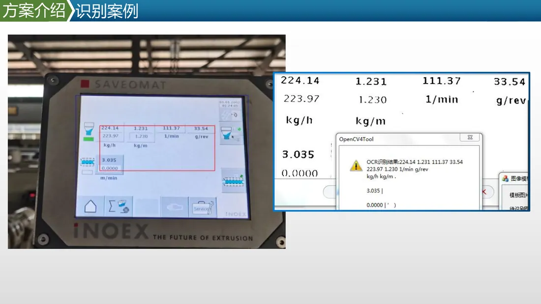
Figure 2-2 Example of image recognition software results (pointer/digital readings and parsed results)
This solution uses a four-layer architecture: front-end explosion-proof camera → network transmission → local FTP/recognition server → database/business system. Inside the oil, gas and chemical explosion-proof area, cameras upload scheduled captures to a local FTP server over wired or 4G wireless networks. The instrument recognition software reads the images in real time, performs recognition, and writes the results to a MySQL database or publishes them to the host system over Modbus.
Figure 3-1 Overall architecture of the explosion-proof instrument vision recognition system (isolated deployment of hazardous and safe areas)
3.1 Network Architecture
Intranet mode: explosion-proof cameras connect to an on-site explosion-proof AP or switch over WiFi/Ethernet cable, and photos are uploaded to a local FTP server
4G mode: where Ethernet cables cannot be laid or WiFi coverage is insufficient, cameras connect to the enterprise private network or the public network over 4G
Hybrid mode: some monitoring points use wired connections and some remote/elevated points use 4G, with all data aggregated to the local recognition server
The following are several typical access architecture diagrams provided by the manufacturer:
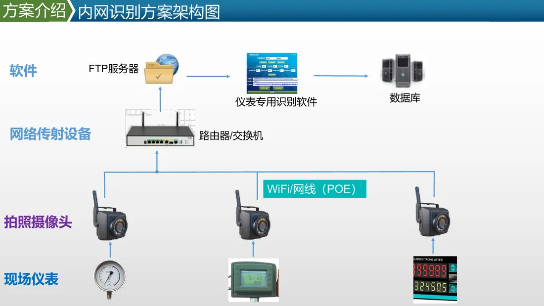
Figure 3-2 Intranet recognition architecture (WiFi/Ethernet cable + POE, FTP upload)
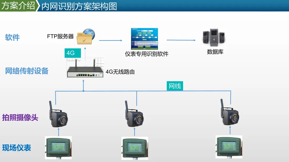
Figure 3-3 4G wireless access architecture (4G wireless router backhaul)
3.2 Data Flow
Cameras automatically capture instrument photos at a set cycle (e.g., 5 min / 15 min / 30 min)
Photos are uploaded via FTP to a designated directory on the local recognition server
The instrument recognition software automatically reads the images and performs recognition
Recognition results are written to the MySQL database and published externally through Modbus Server/Client
DCS/SCADA/MES obtain real-time data through the database or the Modbus interface
4.1 Explosion-Proof Scheduled-Capture Camera
Use the Daq IoT explosion-proof scheduled-capture camera (the explosion-proof version of the 4G/WiFi wireless scheduled-capture camera). It must meet the explosion-proof rating required at oil, gas and chemical sites. The camera body should use a stainless steel explosion-proof enclosure with an explosion-proof wiring chamber and explosion-proof cable glands, suitable for explosive gas atmospheres.
Figure 4-1 Appearance of the scheduled-capture camera (4G/WiFi with matching antenna; the explosion-proof version uses a flameproof enclosure)
| Parameter | Specification |
|---|---|
| Explosion-Proof Rating | Ex db IIC T6 Gb, Ex tb IIIC T80°C Db |
| Power Supply | DC 12 V (inner positive, outer negative; connector DC5.5×2.1mm) or POE |
| Communication | WiFi / 4G / Ethernet |
| Pixels | 2 to 8 megapixels optional, 5 megapixels recommended |
| Lens | 2.8 mm / 4 mm / 6 mm optional, configured as needed |
| Fill Light | Built-in infrared/white LED fill light, supporting night capture |
| Storage | Supports local SD card storage and FTP server upload |
| Protection Rating | IP65 or higher, rainproof and dustproof |
| Operating Temperature | 30 °C to 70 °C |
| Mounting | Bracket fixing or clamp fixing |
4.2 Lens Selection Recommendations
Select the lens according to the installation distance between camera and instrument and the instrument size, using the table below:
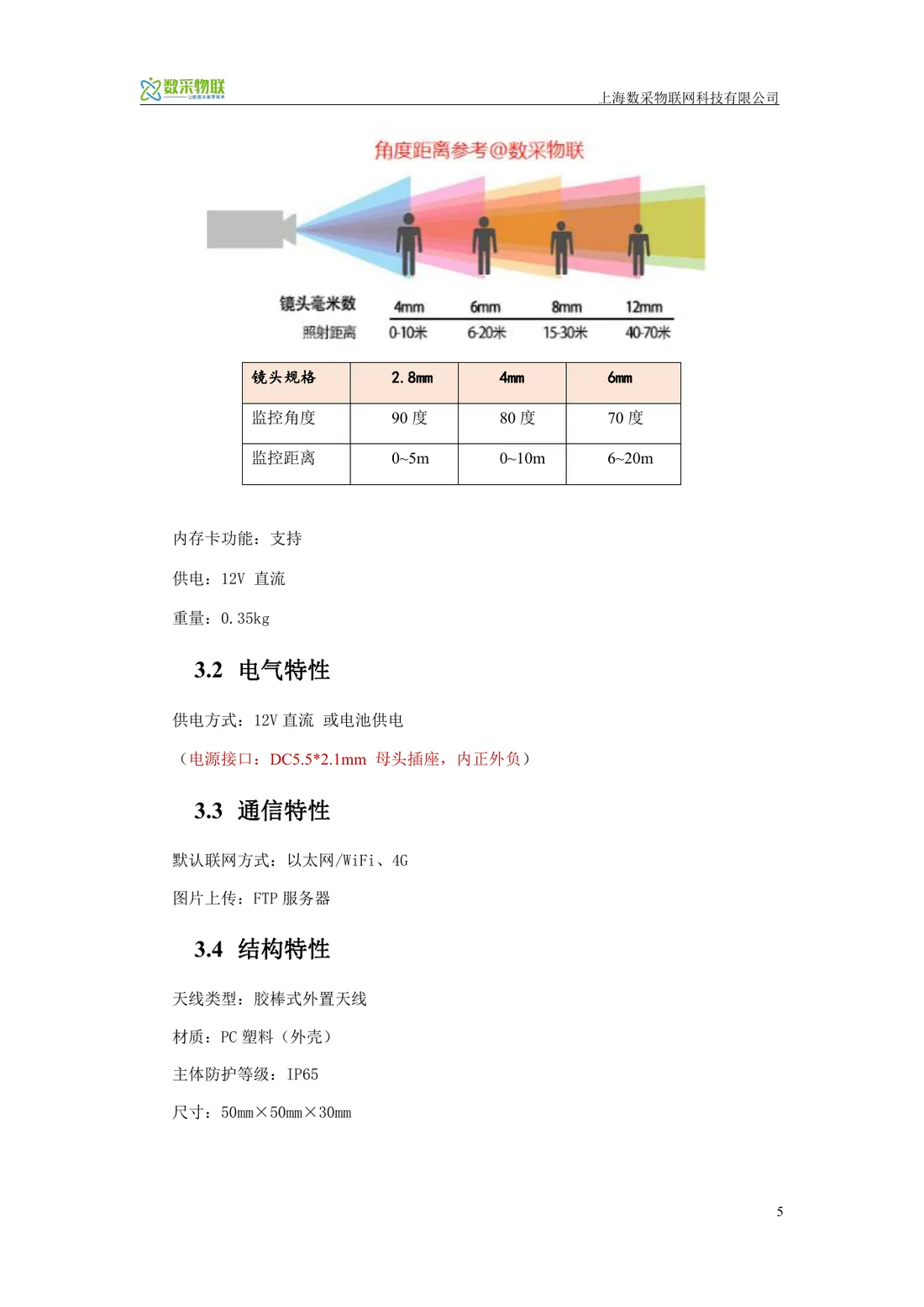
Figure 4-2 Lens focal length vs. monitoring angle/distance
| Lens Specification | Monitoring Angle | Monitoring Distance | Applicable Scenario |
|---|---|---|---|
| 2.8 mm | 90° | 0 to 5 m | Close-up capture of small dials |
| 4 mm | 80° | 0 to 10 m | Analog dial thermometers, close-range level gauges |
| 6 mm | 70° | 6 to 20 m | Full-view capture of distant magnetic flap level gauges |
4.3 Other Supporting Equipment
Explosion-proof mounting bracket: 304 stainless steel, adjustable tilt and horizontal angles, suitable for different installation positions
Explosion-proof distribution box: built-in AC 220 V / DC 12 V power module, circuit breaker, surge protector and terminal blocks
Explosion-proof flexible conduit: used where cables enter explosion-proof equipment from cable trays or buried pipes, to avoid damage from hard pulling
Explosion-proof cable gland: works with the explosion-proof enclosure to ensure flameproof joint surfaces and sealing
Industrial switch / 4G router: selected according to on-site network conditions; must meet installation requirements in explosion-proof areas
Recognition server: industrial PC or server running Windows with the VS2015 runtime installed
Cable routing in oil, gas and chemical explosion-proof areas must meet explosion-proof, fire-proof, corrosion-resistant and mechanical-damage-resistant requirements. This solution involves two cable types, power cables and signal transmission cables, whose routing paths and protection measures need to be planned separately.
Figure 5-1 Schematic of explosion-proof cable routing and local power tapping (power cables in galvanized steel conduit, signal cables in conduit, reliable equipment grounding)
5.1 Power Circuits
Power type: AC 220 V (from an on-site explosion-proof distribution box or a nearby maintenance power supply) → converted to DC 12 V inside the explosion-proof distribution box → explosion-proof camera
Cable selection: use flame-retardant, fire-resistant cables for power (such as ZR-YJV22 and NH-YJV), protected by galvanized steel conduit or explosion-proof flexible conduit
Routing method: lay cables along existing cable trays, through conduit risers, or in buried steel pipes; strictly avoid crossing or running closely parallel to high-temperature or process pipelines
Explosion-proof wiring: all connections must be made inside explosion-proof junction boxes or distribution boxes, sealed with explosion-proof cable glands to keep flameproof surfaces intact
Grounding protection: the explosion-proof distribution box, camera enclosure and steel pipes must all be reliably grounded, with grounding resistance ≤4 Ω; instrument system grounding should be set up independently
5.2 Signal Transmission Lines
Wired: use Category 5e/Category 6 shielded twisted pair (STP) or fiber optic cable, laid in galvanized steel conduit and connected to an on-site explosion-proof switch
Wireless: cameras transmit over WiFi/4G, which reduces on-site cabling, but wireless coverage and network security must be ensured; antennas should be explosion-proof or installed in the safe area
Fiber optic option: for long distances or areas with strong electromagnetic interference, use fiber optic cable with media converters to improve transmission reliability
Network security: 4G access can use an APN private network or a VPN encrypted tunnel to keep production data off the public network
5.3 Cable Routing Precautions
Minimize intermediate joints in cable runs within explosive hazardous areas; where a joint is necessary, make it inside an explosion-proof junction box
Where cables pass between different explosive hazardous areas or different fire compartments, apply firestop sealing
Connect steel pipes with threaded joints coated with conductive paste to ensure electrical continuity; thread engagement must be at least 5 turns
Cable bending radius must meet code requirements to avoid damaging insulation; armored cables must be reliably grounded
Hang identification tags on all cables, showing start point, end point, voltage level and purpose
Explosion-proof cameras need a stable DC 12 V power supply, and local power tapping is a key step in implementing this solution. Choose a safe, reliable power tapping method that complies with explosion-proof codes, based on actual site conditions.
6.1 Principles for Selecting the Power Tapping Point
Prefer the explosion-proof maintenance power box, local control box or instrument distribution box closest to the installation point
The tapping circuit should have its own circuit breaker protection, with capacity meeting the camera and fill light power demand (reserve 30 to 50 W per camera)
The tapping point should be in a non-hazardous area or inside equipment with the appropriate explosion-proof rating; unauthorized wiring is strictly prohibited
If no nearby power source exists, run a dedicated power cable from the area distribution room or cabinet room
6.2 Typical Power Tapping Methods
Method 1: take AC 220 V from a local explosion-proof maintenance power box and convert it to DC 12 V in an explosion-proof distribution box; suitable for most sites
Method 2: tap power from the instrument UPS distribution circuit so the recognition system keeps working for a short time during a mains outage
Method 3: at remote monitoring points with no available power or explosion-proof power source, use an explosion-proof lithium battery pack plus solar panel (explosion-proof compliance and maintenance intervals must be evaluated)
6.3 Power Capacity Calculation
Assume a single explosion-proof camera consumes about 5 to 10 W (capture plus transmission peak) and the fill light about 5 W. Reserve 15 W for single-point operation and allow 30 W for startup and transmission peaks. With an AC 220 V to DC 12 V adapter at 80% efficiency, the AC-side consumption of one camera is about 19 W. Configure an independent 2 A DC 12 V output power module for each camera and reserve a margin of more than 20%.
The Daq IoT instrument recognition software serves as the local recognition engine. It is portable software that supports multiple data sources such as local directories, FTP, HTTP and CGI, and automatically recognizes analog gauges and level gauges.
7.1 Software Operating Environment
Operating system: Windows 7/10/Server 2012 or later
Runtime: VS2015 runtime library must be installed
Hardware: i5 or better CPU, 8 GB RAM and SSD recommended; adjust according to the number of connected cameras
Database: supports MySQL for storing recognition results and historical data
7.2 Software Deployment Modes
FTP mode: cameras upload scheduled captures to the server via FTP, and the recognition software monitors the directory and recognizes automatically
CGI mode: the software is configured to connect to cameras automatically, capture images on a schedule, and store and recognize them
Service mode: after configuration, switch to service mode for automatic startup on boot, automatic restart and continuous background operation
7.3 Recognition Template Configuration
Create separate recognition templates in the software for analog dial thermometers and magnetic flap level gauges:
Add data source: configure the data source name and select a local directory or FTP path
Add recognition template: enter the instrument name (e.g., “T-101 thermometer”, “V-201 level gauge”) and save the parameters
Region recognition: select a sample image, enable region selection, and draw a region of interest around the dial or level gauge display area
Sub-region selection: for analog gauges, draw regions of interest around the pointer and scale; for level gauges, around the scale and the flap boundary area
Preprocessing parameters: adjust Gaussian filtering, edge detection, binarization threshold, brightness and contrast to improve the recognition rate
Recognition test: after saving the template, click recognition test to verify reading accuracy, and refine the OCR template if necessary
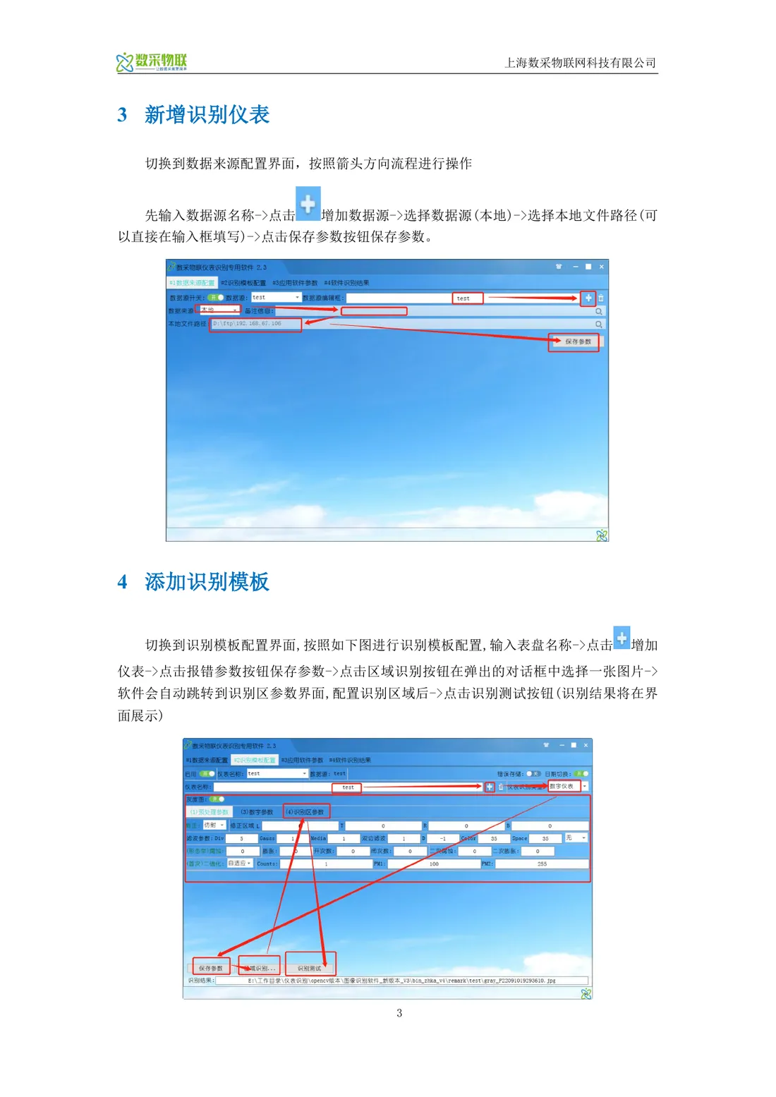
Figure 7-1 Software “Add Instrument / Add Template” configuration screen
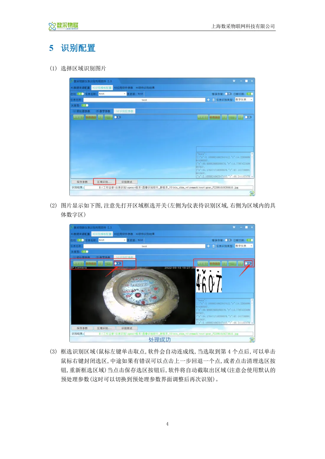
Figure 7-2 Recognition region selection (left: region to be recognized; right: specific digit sub-regions)
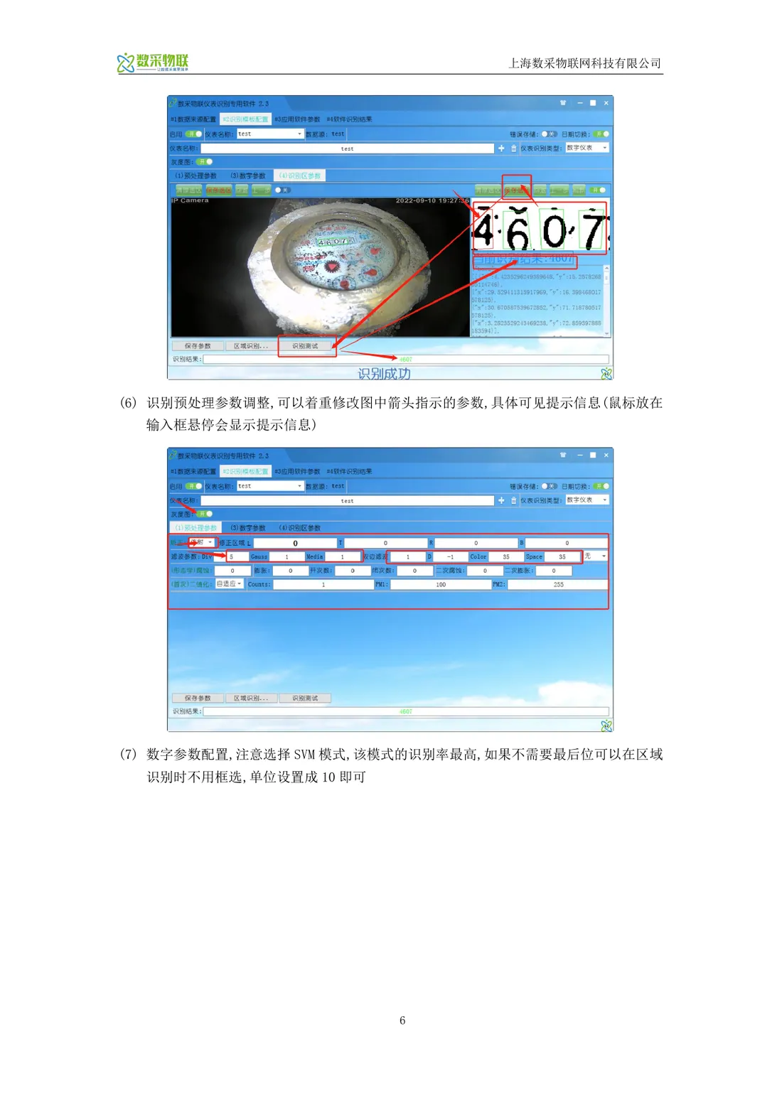
Figure 7-3 Recognition results and preprocessing parameter adjustment screen (SVM mode gives the highest recognition rate)
Figure 8-1 Explosion-proof camera installation position and capture diagram (analog gauge shot straight-on from above; level gauge aligned horizontally with the full range in view)
Step 1: Site survey. Confirm the installation position of each instrument, power tapping point, network access point, explosion-proof zone classification and lighting conditions.
Step 2: Solution design. Based on the survey, determine camera installation positions, lens focal lengths, cable routes and explosion-proof distribution box locations.
Step 3: Equipment procurement. Purchase explosion-proof cameras, brackets, explosion-proof distribution boxes, cables, explosion-proof fittings and so on.
Step 4: Cable routing. Lay power and signal cables per code, with proper grounding, firestop sealing and labeling.
Step 5: Equipment installation. Install explosion-proof distribution boxes and camera brackets, fix the cameras and adjust angles so the instruments face the field of view squarely.
Step 6: Network configuration. Configure camera IP, FTP parameters and WiFi/4G access parameters, and test photo uploads.
Step 7: Software deployment. Install the runtime and recognition software on the recognition server, and configure data sources and recognition templates.
Step 8: Template calibration. Perform region selection, preprocessing parameter tuning and recognition tests for each instrument.
Step 9: Joint commissioning test. Test interfaces with DCS/SCADA/MES and verify data refresh, alarming and storage functions.
Step 10: Training and handover. Train O&M personnel on operation, hand over technical documents, and move into the trial run.
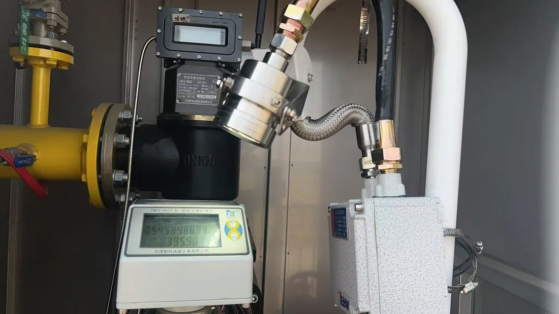
Figure 8-2 On-site installation case reference (camera fixed close to the local instrument)
9.1 Analog Dial Thermometers
Capture angle: keep the camera optical axis as perpendicular to the dial plane as possible, with deviation within ±15°
Capture distance: keep the dial at 1/3 to 1/2 of the image width; recommended distance 0.3 to 1.0 m
Fill light: enable camera fill light to avoid reflections from the dial glass; increase exposure at night or in backlit scenes
Recognition algorithm: use pointer detection + scale matching, set the range to −30 °C to 100 °C, and set the scale division according to the actual instrument
Exception handling: set a reading fluctuation threshold; when anomalies occur repeatedly in succession, mark recognition as failed and raise an alarm
9.2 Magnetic Flap Level Gauges
Capture angle: aim the camera horizontally at the level gauge standpipe to avoid height-proportion distortion from looking up or down
Capture distance: choose the lens according to the range so the full range of the level gauge is clearly visible in the image
Installation height: mount the camera level with the middle of the level gauge to reduce perspective distortion
Recognition algorithm: use edge/color detection to locate the flap boundary line, and calibrate pixel-to-height against the scale marks
Environmental interference: avoid overexposed sky backgrounds, steel structure obstruction, wind-induced sway and similar factors
All electrical equipment entering explosion-proof areas must have a valid explosion-proof certificate
Before construction, obtain work permits for hot work, electrical work, work at height and confined spaces, and implement safety measures
Construction personnel should wear anti-static workwear and use explosion-proof tools; non-explosion-proof electronic devices are strictly prohibited in explosion-proof areas
After installing explosion-proof equipment, check that flameproof surfaces, fasteners and seals are intact; unauthorized disassembly is strictly prohibited
Commissioning and O&M should take place after unit shutdown or with isolation measures in place, to avoid operations that could affect safety during operation
Set up an equipment ledger and an inspection system, and regularly check cables, grounding, camera operating status and recognition accuracy
| Risk Point | Impact | Countermeasure |
|---|---|---|
| No local power source | Camera cannot be powered | Survey power tapping points in advance; if necessary, run a dedicated cable from the distribution room or use an explosion-proof UPS/solar solution |
| Poor network signal | Photo upload fails | Prefer wired networks; add explosion-proof antennas or additional base stations/APs at 4G monitoring points |
| Instrument surface reflections/stains | Recognition rate drops | Adjust the capture angle to avoid reflections; add a light shield; clean the dial regularly |
| Installation angle deviation | Reading error | Use software tilt correction and template calibration; precisely adjust the bracket on site |
| Severe weather | Water ingress/condensation in equipment | Use equipment with a high protection rating; add rain covers; ensure proper sealing |
| Explosion-proof compliance | Acceptance failure | Select and install strictly per GB 50058 and GB 3836; keep explosion-proof certificates and inspection records |
The following list is a reference for a single monitoring point; actual quantities depend on the number of on-site instrument monitoring points. Prices are estimates and the final purchase quotation prevails.
| No. | Equipment/Material | Unit | Qty | Remarks |
|---|---|---|---|---|
| 1 | Explosion-proof scheduled-capture camera (with lens) | unit | 5 megapixels, WiFi/4G optional | |
| 2 | Explosion-proof camera mounting bracket | set | 304 stainless steel, adjustable angle | |
| 3 | Explosion-proof distribution box | unit | Includes AC 220 V / DC 12 V power supply, circuit breaker, surge protection | |
| 4 | Explosion-proof flexible conduit | m | Based on actual installed length | |
| 5 | Explosion-proof cable gland | pc | Matches cable specifications | |
| 6 | Power cable | m | Flame-retardant cables such as ZR-YJV22 | |
| 7 | Network cable / fiber optic cable | m | Category 5e shielded cable or fiber optic cable | |
| 8 | Galvanized steel pipe and fittings | m | Cable protection | |
| 9 | Industrial switch / 4G router | unit | Configured per the network plan | |
| 10 | Recognition server / industrial PC | unit | Runs recognition software; can be shared by multiple monitoring points | |
| 11 | Instrument recognition software | set | License included | |
| 12 | Construction consumables | lot | 1 | Cable ties, identification tags, grounding wires, etc. |
Built on explosion-proof scheduled-capture cameras and local instrument recognition software, this solution provides a safe, reliable, non-contact automatic recognition solution for analog dial thermometers and magnetic flap level gauges in oil, gas and chemical plants. It fully accounts for implementation factors such as cable routing in explosion-proof areas, local power tapping, network transmission and recognition algorithm adaptation. Camera mounting, network architecture and power supply can be adjusted flexibly to actual site conditions. Before formal implementation, carry out a detailed on-site survey and prototype testing to optimize equipment selection and installation positions, ensure long-term stable operation, and meet production safety management requirements.