
Technical and installation plan
Background and requirements
The task is to collect electricity consumption data from the power meters of a metro power distribution system. Traditionally this has been done by manual meter reading, which is labor-intensive, tedious to record and often produces garbled or illegible entries. The requirement is to acquire the meter data automatically: the meters are CT-1500 series units speaking Modbus RTU. An acquisition device is added to each meter and the data is sent over 4G to the corresponding cloud data platform.
Acquisition product
Product composition: 1) power adapter (220 VAC to 12 VDC); 2) 4G module (the acquisition and transmission unit); 3) 4G magnetic-mount antenna. The complete product is shown below.
By default the product reports (refreshes) data to the platform at a 5-minute interval; the interval can be changed remotely to 5 minutes or longer.
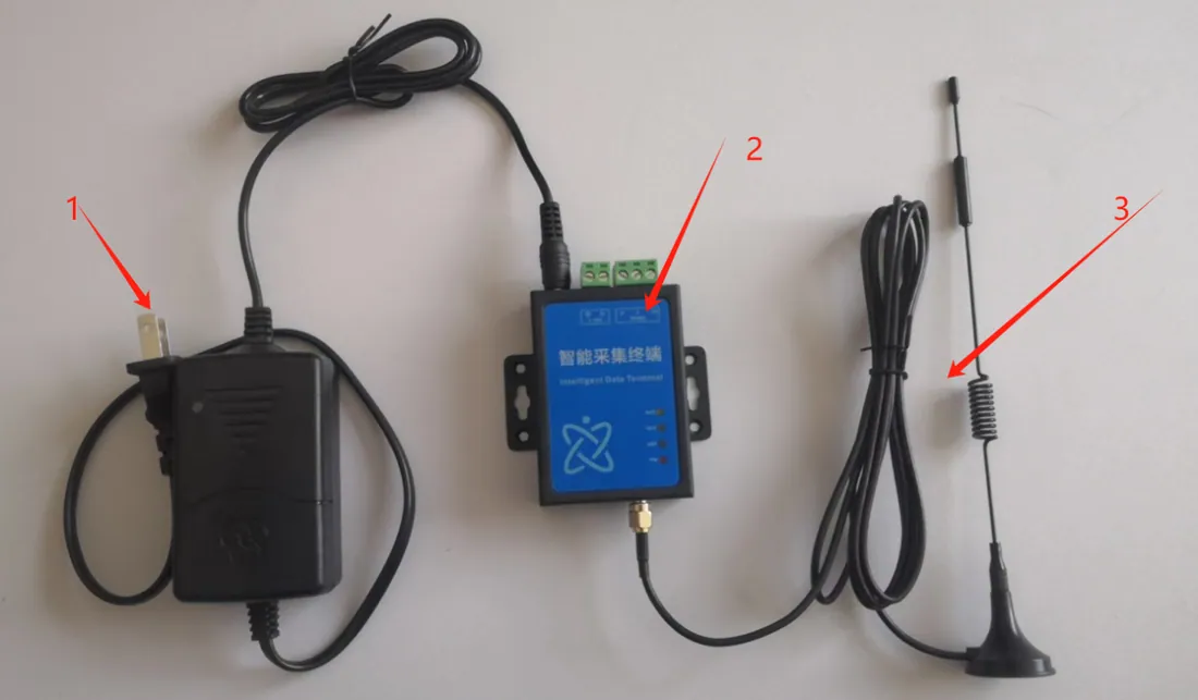
Figure 1 — Complete product
Note: when installing, select a 485 communication cable of a length that suits the site.
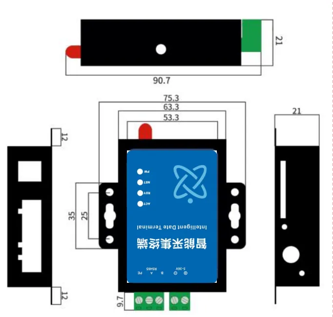
Figure 3 — Dimensions of the main unit
Acquisition method, installation advantages and site considerations
3.1 Technical approach
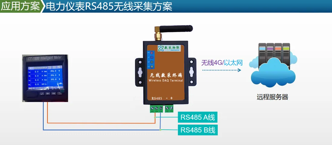
Figure 4 — System topology
The meter’s RS485 interface (terminals 15 and 16 are 485A and 485B respectively) is wired to a 4G smart acquisition terminal. The terminal parses the data and transmits it wirelessly to the backend cloud server. On site only the 485 connection and the device power supply are needed; technicians then configure the backend remotely to complete the acquisition task.
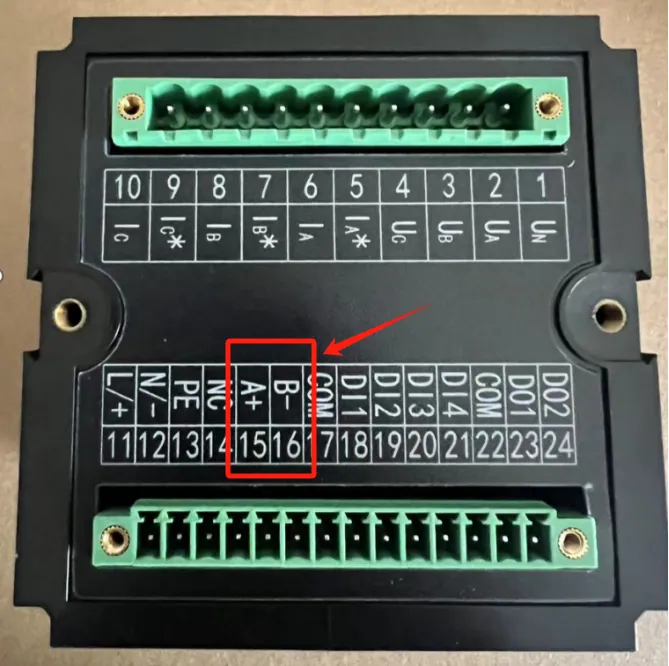
Figure 5 — RS485 interface on the power meter
3.2 Installation advantages
Simple installation and fast deployment, which helps IoT projects go live quickly.
Custom registration and heartbeat packets are supported, so the platform can tell devices apart easily.
Works with any IoT cloud platform or SCADA software, with data protocol integration provided.
Supports mainstream cloud platforms such as Alibaba Cloud, Baidu Tiangong, OneNET and Tencent Cloud.
Supports external connection of multiple sensors.
Remote parameter configuration and FOTA firmware upgrades keep the cost of on-site service visits to a minimum.
3.3 Factors that affect installation
- The meter must be openable for wiring (not blocked by a seal) and its RS485 port must be free.
Signal: the environment around the meter matters — a basement distribution cabinet, for example, affects 4G reception (with no signal, no data can be transmitted). For fully sealed sheet-steel cabinets the antenna must be routed outside; a longer antenna cable can be used.
Power: 220 VAC or 12 VDC must be available on site.
Data platform display
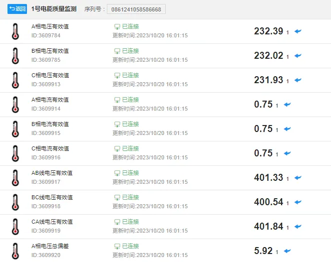
Installation plan
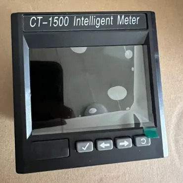
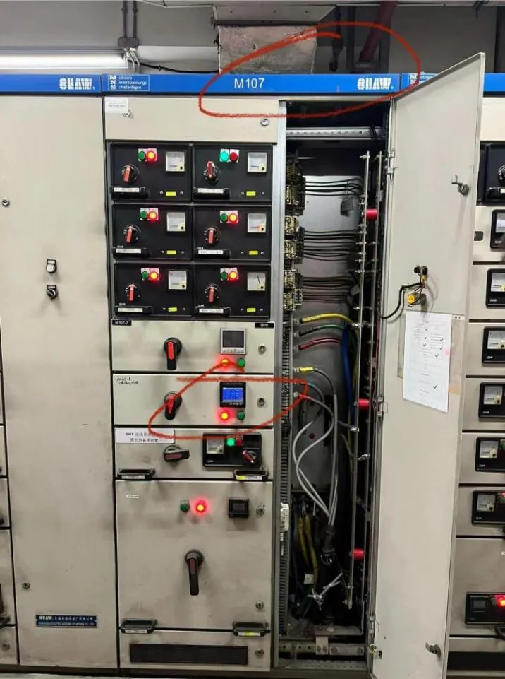
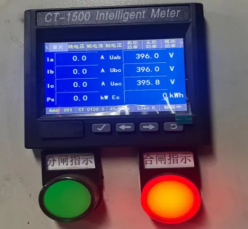
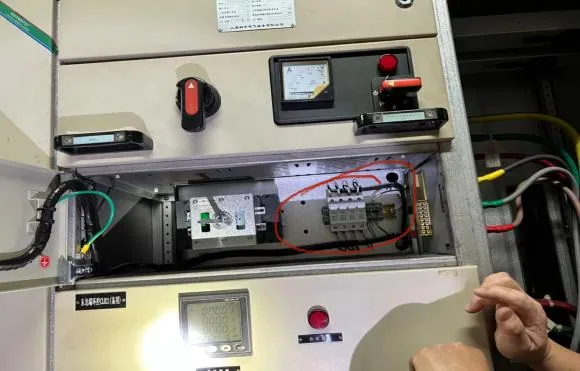
Site meter environment and example photos
The power adapter (220 VAC to 12 VDC) requires a 220 V supply (AC or DC) and is fed from the lower terminal of the fuse inside the fixed-type drawer shown in Figure 3.
The 4G module (the acquisition and transmission unit) is compact and can be mounted directly on the base panel in front of the fuse or the switch inside the fixed-type drawer shown in Figure 3 (this can be done at the same time as the drawer retrofit).
After installation, route the 4G antenna lead to the top of the cabinet shown in Figure 1 to improve signal strength.
Each product carries a unique identifier and can be paired with a phone or tablet on site (with the Daq IoT application installed), which then displays that device’s data.
Installation complete.
Installation safety measures
-
Inspect tools before use and replace any that are defective immediately.
-
A supervisor must be present during the work, taking responsibility for quality and safety throughout the operation.
-
Personnel must wear the necessary personal protective equipment — work clothing, safety shoes, gloves, helmet and so on.
-
Isolate and test for voltage before starting work, and proceed only once the circuit is confirmed dead.
-
Attach a “Men at work — do not switch on” warning tag and a lock to the breaker or switch, and install a grounding conductor on the busbar side.
-
Erect isolation barriers around the work area to prevent accidental contact with adjacent live compartments.
-
Begin work only after every safety measure is in place.
-
When work is carried out simultaneously on more than one trade or level, never allow two work fronts on the same vertical face. Follow the “three no-harm” principle (do not harm yourself, do not harm others, do not let others harm you), avoid habitual unsafe practice, and coordinate the timing of simultaneous operations.
-
After the work, carry out insulation checks and clear the site: remove and dispose of all waste, debris and temporary tools and equipment, leaving the area clean and tidy.
-
Avoid working while fatigued; rotate staff who are not fit for the task, and never allow anyone who has been drinking or is unwell to work in the cable trench.
-
On completion, self-inspect the work and then have the customer’s responsible person confirm it. Only then may the circuit be energized for commissioning.
After-sales service
We are committed to service quality: the company has documented service procedures and after-sales rules, and requires service staff to be warm, sincere, patient, meticulous and prompt. We respond to after-sales requests 24 hours a day. For routine requests, a contact person is assigned the same day the call comes in and resolves the issue. For urgent or special requests, we guarantee a response within 2 hours of the call and arrival on site within 6 hours to resolve the problem and keep the customer’s product working. After completing any service visit, the engineer fills in the company’s after-sales feedback form, describing what was reported and the measures taken to resolve the quality issue, has the customer confirm and sign it, and returns it to the company for filing.